Copyright © 2026 Akamai Technologies Canada Inc.
Permission is granted to copy, distribute and/or modify this document under the terms of the GNU Free Documentation License, Version 1.2 or any later version published by the Free Software Foundation; with no Invariant Sections, no Front-Cover Texts, and no Back-Cover Texts. A copy of the license is included in the section entitled "GNU Free Documentation License".
The fonts used in this guide are licensed under the SIL Open Font License, Version 1.1. This license is available with a FAQ at: http://scripts.sil.org/OFL
Copyright © Raph Levien, http://levien.com/, with Reserved Font Name: "Inconsolata".
1. About this Guide
This guide covers network device configuration for VLAN enforcement and access control with PacketFence. It provides device-specific configuration instructions for over 80 supported network vendors including managed switches, wireless controllers, and wireless access points. The guide covers 802.1X authentication, MAC authentication bypass, VLAN assignment, RADIUS configuration, and SNMP integration with various network equipment manufacturers.
Find the latest version at https://www.packetfence.com/docs/
1.1. Other Guides
- Clustering Guide
-
Comprehensive guide for setting up active/active clustering environments with HAProxy load balancing, Keepalived for high availability, and Galera database clustering. Includes advanced configuration for layer-3 clusters and troubleshooting cluster synchronization issues.
- Developer’s Guide
-
Technical documentation for customizing PacketFence including REST API usage, captive portal theming and functionality modifications, SNMP module development, supporting new network equipment, and application code customizations. Essential for integrators and developers extending PacketFence.
- Installation Guide
-
Complete installation and configuration guide covering standalone deployments, system requirements, network planning, authentication integration (Active Directory, LDAP, RADIUS), certificate management, and initial system setup. Includes troubleshooting and advanced configuration topics.
- Upgrade Guide
-
Step-by-step upgrade procedures with version-specific compatibility changes, manual configuration migration steps, database schema updates, and critical upgrade notes. Includes troubleshooting for common upgrade issues and rollback procedures.
1.2. Other sources of information
- https://www.packetfence.com/news
-
Release announcements with detailed feature descriptions, performance improvements, security updates, and comprehensive bug fix listings organized by PacketFence version.
- PacketFence Users Mailing List
-
Community support forum for installation help, configuration questions, troubleshooting assistance, and best practices discussions. Active community of users and developers providing peer-to-peer support.
- PacketFence Announcements
-
Public announcements including new releases, security warnings and important updates regarding PacketFence. Low-traffic list for staying informed about major PacketFence developments.
- PacketFence Development
-
Discussion of PacketFence development including feature requests, architectural discussions, patch submissions and development coordination. For developers contributing to PacketFence core.
Package and release tarballs include the PacketFence guide files.
2. Important Notes
2.1. Inline enforcement support
Inline enforcement does not require this guide, except for RADIUS inline. RADIUS inline uses a flat layer-2 network on PacketFence’s inline interface with no other gateway for Internet access.
Use this technique when network hardware does not support VLAN enforcement.
2.2. RADIUS accounting
Enabling RADIUS accounting on network devices significantly increases database size and may cause performance issues. Use RADIUS accounting only if absolutely required.
2.3. Supported Network Devices
PacketFence supports numerous wireless and wired network equipment from various vendors running different versions. For accurate information without duplication, refer to our website https://www.packetfence.com/self-host/compatible-switches/
This page lists enforcement modes supported by all tested equipment.
3. Switch configuration
3.1. Assumptions
Network infrastructure assumptions for this configuration:
- PacketFence fully configured with FreeRADIUS running (for 802.1X or MAC Auth)
- PacketFence IP address: 192.168.1.5
- Normal VLAN: 1
- Registration VLAN: 2
- Isolation VLAN: 3
- MAC Detection VLAN: 4
- Guest VLAN: 5
- VoIP, Voice VLAN: 100
- use SNMP v2c
- SNMP Read community: public
- SNMP Write community: private
- SNMP Trap community: public
- RADIUS Secret: useStrongerSecret
3.2. 3COM
3.2.1. SuperStack 3 Switch 4200 and 4500
PacketFence supports these 3Com switches without VoIP using one trap type:
- linkUp===linkDown
- Port Security (with static MACs)
Don’t forget to update the startup config!
linkUp === linkDown only
Global config settings:
snmp-agentsnmp-agent target-host trap address udp-domain 192.168.1.5 params securitynamepublicsnmp-agent trap enable standard linkup linkdown
On each interface:
port access vlan 4
In Port Security
Global config settings:
snmp-agentsnmp-agent target-host trap address udp-domain 192.168.1.5 params securitynamepublicsnmp-agent trap enableport-security enableport-security trap addresslearnedport-security trap intrusion
On each interface:
port access vlan 4port-security max-mac-count 1port-security port-mode secureport-security intrusion-mode blockmacundo enable snmp trap updown
In MAC Auth
Voice vlan : 6Normal vlan : 1Registration vlan : 2Isolation vlan : 3
Global config settings:
lldp enablelldp timer tx-interval 5lldp compliance cdplldp compliance cdp
port-security enableMAC-authentication domain packetfence
radius scheme systemradius scheme packetfenceserver-type extendedprimary authentication 192.168.1.5primary accounting 192.168.1.5key authentication P@cketfencekey accounting cipher P@cketfenceuser-name-format without-domain
domain packetfenceauthentication radius-scheme packetfenceaccounting radius-scheme packetfencevlan-assignment-mode stringaccounting optionaldomain system
voice vlan mac-address f4ea-6700-0000 mask ffff-ff00-0000 description Cisco IPPhoneundo voice vlan security enablevoice vlan 6 enable
On each interface with VoIP:
interface Ethernet1/0/1stp edged-port enablelldp compliance admin-status cdp txrxport link-type hybridport hybrid vlan 6 taggedport hybrid vlan 1 2 3 untaggedundo voice vlan mode autovoice vlan enableport-security max-mac-count 3port-security port-mode mac-authenticationport-security intrusion-mode blockmacundo enable snmp trap updown
3.2.2. E4800G
PacketFence supports these 3Com switches with the following techniques:
- 802.1X with MAC Authentication fallback
- linkUp/linkDown (not recommended)
Voice over IP support was not explicitly tested during implementation however it does not mean that it won’t work.
Don’t forget to update the startup config!
linkUp / linkDown only
Global config settings:
snmp-agentsnmp-agent target-host trap address udp-domain 192.168.1.5 params securitynamepublicsnmp-agent trap enable standard linkup linkdown
On each interface:
port access vlan 4
802.1X with MAC Authentication fallback
Global config settings:
system-viewradius scheme PacketFenceprimary authentication 192.168.1.5 1812primary accounting 192.168.1.5 1812key authentication useStrongerSecretuser-name-format without-domainquitdomain packetfence.localauthentication default radius-scheme PacketFenceauthorization default radius-scheme PacketFencequitdomain default enable packetfence.localdot1x authentication-method eapport-security enablequit
If your management authentication on your switch is default, applying the configuration above will have your authentication switch to a RADIUS based one with PacketFence as the authentication server. It is almost certain that you do not want that!
Below, we will just create a local password for vty accesses (telnet) and
nothing on the console. In order to avoid locking yourself out, make sure
to verify your configuration!
system-viewuser-interface aux 0authentication-mode noneuser-interface vty 0 4user privilege level 3set authentication password simple useStrongerPasswordquitquit
On each interface:
system-viewinterface gigabitEthernet 1/0/xxport-security port-mode mac-else-userlogin-secure-ext# userlogin-secure-or-mac-ext could be used below instead# see the Switch_4200G's documentation for a discussion about itundo enable snmp trap updownquitquit
where xx stands for the interface index.
3.2.3. E5500G and Switch 4200G
PacketFence supports these 3Com switches with the following techniques:
- 802.1X with MAC Authentication fallback
- linkUp/linkDown (not recommended)
Voice over IP support was not explicitly tested during implementation however it does not mean that it won’t work.
Don’t forget to update the startup config !
linkUp / linkDown only
Global config settings:
snmp-agentsnmp-agent target-host trap address udp-domain 192.168.1.5 paramssecurityname publicsnmp-agent trap enable standard linkup linkdown
On each interface:
port access vlan 4
802.1X with MAC Authentication fallback
Global config settings:
system-viewradius scheme PacketFenceserver-type standardprimary authentication 192.168.1.5 1812primary accounting 192.168.1.5 1812accounting optionalkey authentication useStrongerSecretuser-name-format without-domainquitdomain packetfence.localradius-scheme PacketFencevlan-assignment-mode stringquitdomain default enable packetfence.localdot1x authentication-method eapport-security enablequit
If your management authentication on your switch is default, applying the configuration above will have your authentication switch to a RADIUS based one with PacketFence as the authentication server. It is almost certain that you do not want that!
Below, we will just create a local password for vty accesses (telnet) and
nothing on the
console. In order to avoid locking yourself out, make sure to verify your
configuration!
system-viewuser-interface aux 0authentication-mode noneuser-interface vty 0 4user privilege level 3set authentication password simple useStrongerPasswordquitquit
On each interface:
system-viewinterface gigabitEthernet 1/0/xxport-security port-mode mac-else-userlogin-secure-ext# userlogin-secure-or-mac-ext could be used below instead# see the Switch_4200G's documentation for a discussion about itundo enable snmp trap updownquitquit
where xx stands for the interface index
3.2.4. NJ220
This switch does not support port-security.
To configure: use the switch web interface to send the linkUp/linkDown traps to the PacketFence server.
3.3. Alcatel
3.3.1. OS6250, OS6450
PacketFence supports this switch using 802.1X, Mac authentication and also supports VoIP.
Global configuration
First define any VLAN that you want to use on the switch.
vlan 2vlan 5vlan 20vlan 100
Next, configure the RADIUS server to be PacketFence
aaa radius-server "packetfence" host 192.168.1.5 key useStrongerSecretaaa authentication mac packetfenceaaa authentication 802.1X packetfence
You now need to configure a user profile (equivalent of a role) that will determine which VLAN is assigned to the device. In this case the profile names are 'unreg', 'employee' and 'guest'.
aaa user-network-profile name unreg vlan 2aaa user-network-profile name guest vlan 5aaa user-network-profile name employee vlan 20
Next, configure the switch in PacketFence. In the case of this example, the uplink is port 1/1.
[192.168.1.10]mode=productiondescription=alcateltype=AlcatelradiusSecret=useStrongerSecretuplink_dynamic=0uplink=1001RoleMap=YVlanMap=NregistrationRole=unregisolationRole=unregdefaultRole=employeeguestRole=guest
802.1X
First, make sure you followed the steps above in 'Global configuration'
You will need to configure the ports you want to do authentication on.
vlan port mobile 1/2vlan port 1/2 802.1X enable802.1X 1/2 supplicant policy authentication pass group-mobility block failblock802.1X 1/2 non-supplicant policy authentication pass group-mobility blockfail block
MAC Authentication
First, make sure you followed the steps above in 'Global configuration' and '802.1X'
Next configure the interface to bypass 802.1X authentication
802.1X 1/2 supplicant bypass enable
VoIP
PacketFence supports VoIP on Alcatel by having multiple devices using multiple untagged VLANs on the same port.
First configure the user profile for voice. In this example it is only isolating it on another VLAN but any user profile attributes can be added to the profile.
aaa user-network-profile name voice vlan 3
Next, make sure you enable VoIP in the switch configuration in PacketFence and configure the voiceRole.
[192.168.1.10]VoIPEnabled=YvoiceRole=voice
3.3.2. OS6860
PacketFence supports this switch using 802.1X, Mac authentication and also supports VoIP.
Global configuration
First define any VLAN that you want to use on the switch.
vlan 2 admin-state enablevlan 5 admin-state enablevlan 20 admin-state enablevlan 100 admin-state enable
Next, configure the RADIUS server to be PacketFence
aaa radius-server "packetfence" host 192.168.1.5 key useStrongerSecretaaa device-authentication mac packetfenceaaa device-authentication 802.1X packetfence
You now need to configure an edge profile (equivalent of a role) that will determine which VLAN is assigned to the device. In this case the profile names are 'unreg', 'employee' and 'guest'.
unp edge-profile unregunp edge-profile unreg redirect enableunp edge-profile unreg authentication-flag enableunp vlan-mapping edge-profile unreg vlan 2
unp edge-profile guestunp edge-profile guest redirect enableunp edge-profile guest authentication-flag enableunp vlan-mapping edge-profile guest vlan 5
unp edge-profile employeeunp edge-profile employee redirect enableunp edge-profile employee authentication-flag enableunp vlan-mapping edge-profile employee vlan 20
Next, configure the switch in PacketFence. In the case of this example, the uplink is port 1/1/1.
[192.168.1.10]mode=productiondescription=alcateltype=AlcatelradiusSecret=useStrongerSecretuplink_dynamic=0uplink=1001RoleMap=YVlanMap=NregistrationRole=unregisolationRole=unregdefaultRole=employeeguestRole=guest
MAC Authentication
First, make sure you followed the steps above in 'Global configuration'
You will need to create an edge template and apply it on the ports you want to do authentication on.
unp edge-template pf_mabunp edge-template pf_mab mac-authentication enableunp edge-template pf_mab classification enableunp port 1/1/2 port-type edgeunp port 1/1/2 edge-template pf_mab
802.1X
First, make sure you followed the steps above in 'Global configuration'
You will need to create an edge template and apply it on the ports you want to do authentication on.
unp edge-template pf_dot1xunp edge-template pf_dot1x 802.1X-authentication enableunp edge-template pf_dot1x mac-authentication enableunp edge-template pf_dot1x 802.1X-authentication failure-policymac-authenticationunp port 1/1/2 port-type edgeunp port 1/1/2 edge-template pf_dot1x
VoIP
PacketFence supports VoIP on Alcatel by having multiple devices using multiple untagged VLANs on the same port.
First configure the edge profile for voice. In this example it is only isolating it on another VLAN but any edge profile attributes can be added to the profile.
unp edge-profile voiceunp edge-profile voice redirect enableunp edge-profile voice authentication-flag enableunp vlan-mapping edge-profile voice vlan 100
Next, make sure you enable VoIP in the switch configuration in PacketFence and configure the voiceRole.
[192.168.1.10]VoIPEnabled=YvoiceRole=voice
3.4. AlliedTelesis
3.4.1. AT8000GS
PacketFence supports the AT8000GS switch using :
- MAC Authentication
- 802.1X
- 802.1X + VOIP
Assumptions
PacketFence management IP: 192.168.1.5Switch management IP: 10.0.0.14Guest VLAN (Internet): VLAN 1
MAC Authentication
First, enable 802.1X globally:
dot1x system-auth-control
Next, configure the RADIUS server and AAA settings:
radius-server host 192.168.1.5radius-server key useStrongerSecretradius-server source-ip 10.0.0.14aaa authentication dot1x default radiusaaa accounting dot1x radius
In order to get mac authentication, you need to enable the guest VLAN globally:
interface vlan 1name "Guest Vlan"dot1x guest-vlanexit
Finally, enable the necessary 802.1X settings for mac-only authentication:
interface ethernet g1dot1x mac-authentication mac-onlydot1x radius-attributes vlandot1x port-control autodot1x guest-vlan enable
802.1X
The settings are almost the same as the MAC Authentication with some small differences.
First, enable 802.1X globally:
dot1x system-auth-control
Next, configure the RADIUS server and AAA settings:
radius-server host 192.168.1.5radius-server key useStrongerSecretradius-server source-ip 10.0.0.14aaa authentication dot1x default radiusaaa accounting dot1x radius
Finally, enable the necessary 802.1X settings:
interface ethernet g1dot1x radius-attributes vlandot1x port-control auto
802.1X + VOIP
First, enable 802.1X globally:
dot1x system-auth-control
Next, configure the RADIUS server configuration and AAA settings:
radius-server host 192.168.1.5radius-server key useStrongerSecretradius-server source-ip 10.0.0.14aaa authentication dot1x default radiusaaa accounting dot1x radius
Then, LLDP configuration:
hostname switch-nameip domain-name domain.locallldp med network-policy 1 voice vlan 100 vlan-type tagged dscp 34lldp med network-policy 2 voice-signaling vlan 100 vlan-type tagged dscp 34
Finally, enable the necessary 802.1X and VOIP settings on each interface:
interface ethernet g1dot1x port-control force-authorizedno dot1x guest-vlan enableno dot1x mac-authenticationno dot1x radius-attributes vlanno dot1x re-authenticationswitchport mode trunkswitchport trunk native vlan 5switchport trunk allowed vlan add 100lldp med enable network-policylldp med network-policy add 1lldp med network-policy add 2
802.1X commands
show dot1x supplicant brief
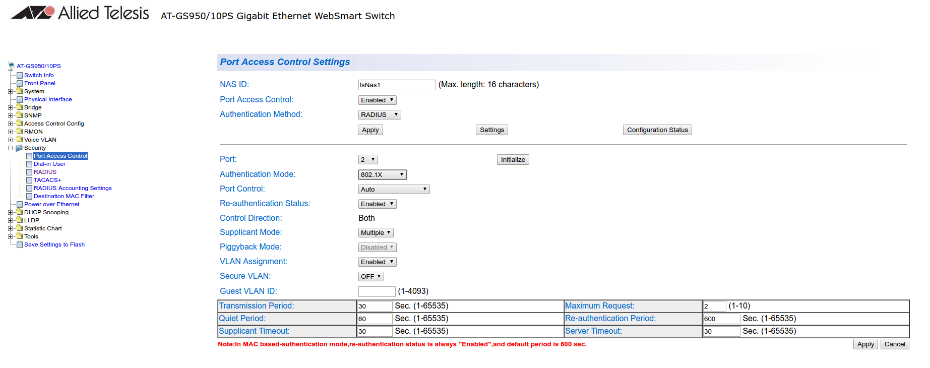
3.4.2. GS950
PacketFence supports the GS950 switch using :
- MAC Authentication
- 802.1X (without fallback to MAC authentication)
Global configuration
First, ensure that the VLANs you want to assign are part of the VLAN database via the following page:
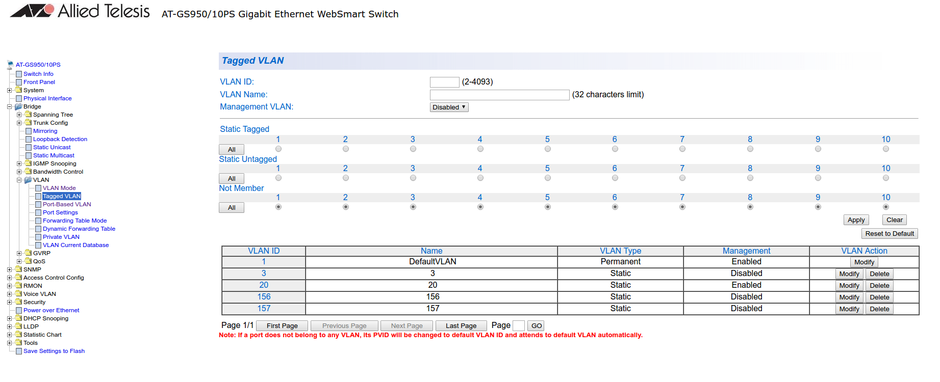
Note that they only need to be tagged on the trunk and don’t need any specific configuration for the dynamic VLAN assignment here.
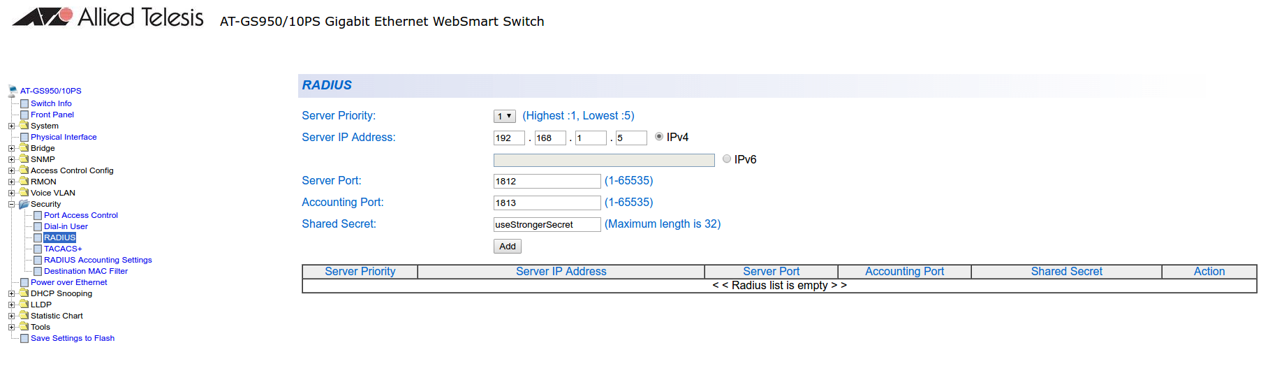
Next, configure the RADIUS server (Security → RADIUS):
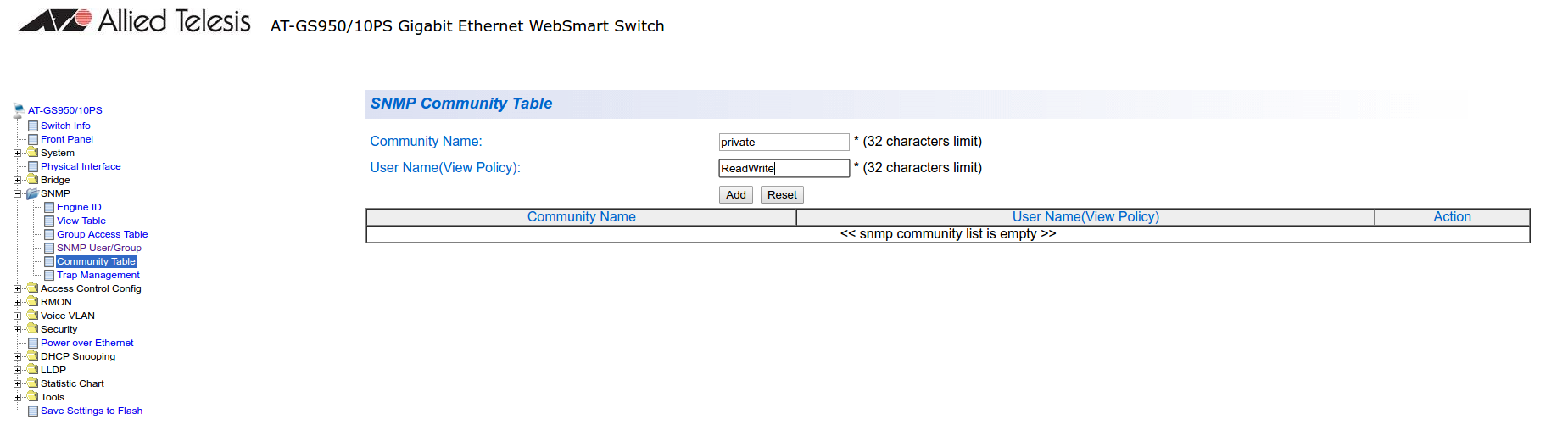
Next, configure an SNMP community (SNMP → Community Table)
MAC authentication
Go in Security → Port Access Control, select the port you want to enable MAB on, and ensure you set:
- Authentication Mode: MAC Based
- Port Control: Auto
- Supplicant Mode: Single
- VLAN Assignment: Enabled
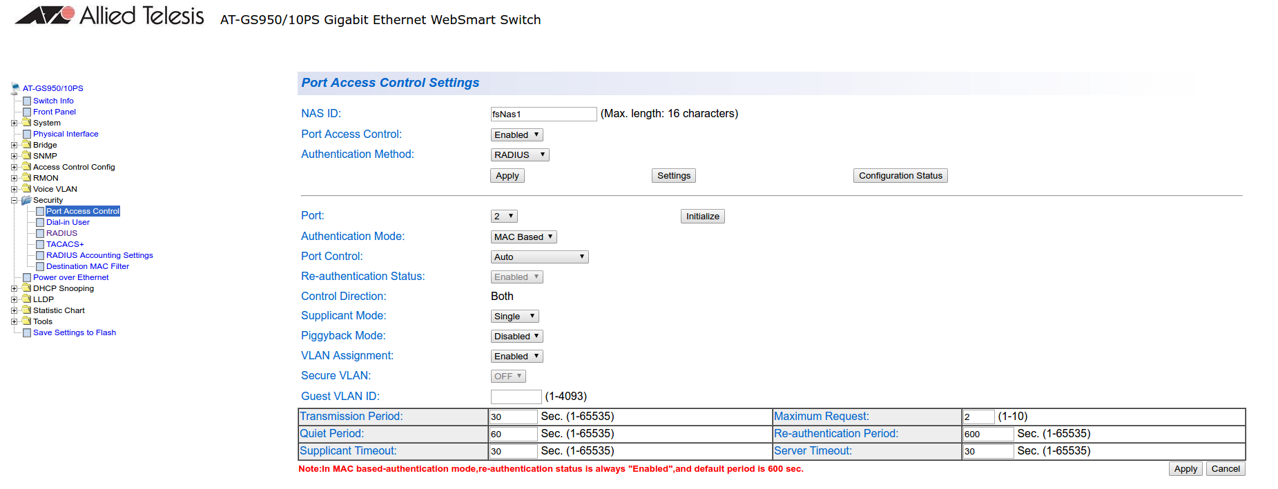
802.1x
Go in Security → Port Access Control, select the port you want to enable MAB on, and ensure you set:
- Authentication Mode: 802.1X
- Port Control: Auto
- Supplicant Mode: Multiple
- VLAN Assignment: Enabled
PacketFence configuration
Ensure you configure at least:
- Type: Allied Telesis GS950
- RADIUS secret: useStrongerSecret
- SNMP Version: v2c
- SNMP Community Read: private
- SNMP Community Write: private
If you are using MAC authentication on this switch, you must adjust the FreeRADIUS configuration so it transforms the EAP requests this switch sends into requests that PacketFence will interpret as MAC authentication. This configuration will also set missing attributes in the RADIUS requests since this switch doesn’t follow the standard attributes that are usually sent during RADIUS authentication.
To adjust it, go in /usr/local/pf/conf/radiusd/packetfence and add the
following below the line that contains packetfence-eap-mac-policy:
packetfence-allied-gs950-mab
And then restart FreeRADIUS:
# /usr/local/pf/bin/pfcmd service radiusd restart
3.5. Amer
PacketFence supports Amer switches without VoIP using one trap type:
- linkUp/linkDown
Don’t forget to update the startup config!
3.5.1. L2 Switch SS2R24i
Global config settings:
create snmp host 192.168.1.5 v2c publiccreate snmp user public ReadGroupenable snmp traps
On each interface:
config vlan default delete xxconfig vlan mac-detection add untagged xx
where xx stands for the interface index
3.6. Arista
3.6.1. Arista EOS
PacketFence supports Arista EOS switches using RADIUS for MAC Authentication (MAB) and 802.1X. Dynamic VLAN assignment, RADIUS Change of Authorization (CoA) and downloadable ACLs (NAS-Filter-Rule) are supported as well as VoIP detection via LLDP-MED.
The minimum required EOS firmware version is 4.29.1F.
Global RADIUS Configuration
Define the PacketFence RADIUS server, the AAA group, the AAA methods used for 802.1X and MAB and enable RADIUS Dynamic Authorization (CoA) so PacketFence can push role/VLAN/ACL changes back to the switch:
radius-server host 192.168.1.5 key useStrongerSecret!aaa group server radius PacketFenceserver 192.168.1.5!aaa authentication dot1x default group PacketFenceaaa authorization network default group PacketFenceaaa accounting dot1x default start-stop group PacketFence!aaa server radius dynamic-authorizationclient 192.168.1.5 server-key useStrongerSecret!dot1x system-auth-control
802.1X with MAC Authentication Bypass (MAB)
Apply the following configuration on each access port that should be authenticated. 802.1X is attempted first; if the supplicant does not respond, the switch falls back to MAC authentication (MAB):
interface Ethernet1switchportswitchport mode accessdot1x pae authenticatordot1x port-control autodot1x host-mode multi-hostdot1x reauthenticationdot1x timeout quiet-period 10dot1x timeout tx-period 5dot1x mac-based authenticationlldp transmitlldp receive
To support multiple devices behind the port (for example a PC behind an IP
phone), use multi-auth instead of multi-host:
dot1x host-mode multi-auth
MAC Authentication only (MAB only)
For ports where 802.1X is not desired (for example printers, IoT, etc.), enable only MAC-based authentication:
interface Ethernet2switchportswitchport mode accessdot1x pae authenticatordot1x port-control autodot1x host-mode multi-hostdot1x reauthenticationdot1x mac-based authenticationdot1x mac-based authentication mac-only
VoIP
Arista EOS uses LLDP-MED to advertise the voice VLAN to IP phones. Make sure LLDP is enabled on the access ports (see the 802.1X section above) and that the voice VLAN is allowed on the port:
interface Ethernet1switchport voice vlan 100
PacketFence will return the Arista-AVPair = device-traffic-class=voice VSA
for nodes identified as VoIP devices.
Uplink
The uplink towards the rest of the network must not authenticate clients:
interface Ethernet48switchport mode trunkswitchport trunk allowed vlan 1-5,100dot1x port-control force-authorized
Dynamic ACL (NAS-Filter-Rule)
The Arista module supports per-role ACLs pushed in the RADIUS Access-Accept
using the NAS-Filter-Rule attribute. To use it:
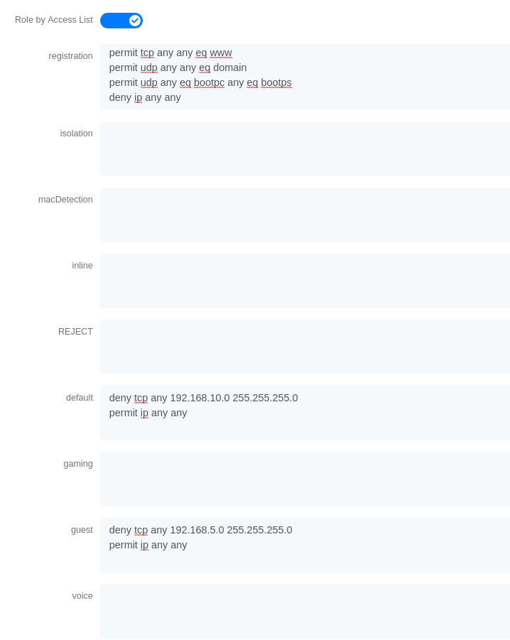
- In Configuration → Policies and Access Control → Switches, edit your Arista switch entry and enable Role by access list.
-
Define the ACL for each role under Configuration → Policies and Access
Control → Roles, for example for the registration role:
permit in tcp from any to 192.168.1.5 80permit in tcp from any to 192.168.1.5 443permit in udp from any to any 53permit in udp from any to any 67deny in ip from any to any
PacketFence switch configuration
In the PacketFence administration interface, add the switch under Configuration → Policies and Access Control → Switches using the following parameters:
-
Type:
Arista EOS -
Mode:
production -
Deauthentication Method:
RADIUS -
RADIUS Secret:
useStrongerSecret
3.7. Aruba
3.7.1. ArubaOS_CX_10.x and ArubaOS_Switch_16.x
The ArubaOS_CX_10.x and ArubaOS_Switch_16.x are supported by PacketFence and it supports MAC Authentication, 802.1X, Dynamic ACLS and Web Authentication.
Global Radius Configuration
radius-server host 192.168.1.5 key "useStrongerSecret"radius-server host 192.168.1.5 dyn-authorizationradius-server host 192.168.1.5 time-window 0ip source-interface radius vlan 1aaa server-group radius "PacketFence" host 10.5.6.100aaa accounting network start-stop radius server-group "PacketFence"
MAC Authentication
aaa authentication mac-based chap-radius server-group "PacketFence"aaa port-access mac-based 1aaa port-access mac-based 1 addr-movesaaa port-access mac-based 1 reauth-period 14400
802.1x
aaa authentication port-access eap-radius server-group "PacketFence"aaa port-access authenticator 1aaa port-access authenticator 1 tx-period 10aaa port-access authenticator 1 client-limit 2aaa port-access authenticator active
MAC Authentication Bypass
aaa authentication mac-based chap-radius server-group "PacketFence"aaa authentication port-access eap-radius server-group "PacketFence"aaa port-access 1 auth-order authenticator mac-basedaaa port-access mac-based 1aaa port-access mac-based 1 addr-movesaaa port-access mac-based 1 reauth-period 14400aaa port-access authenticator 1aaa port-access authenticator 1 tx-period 10aaa port-access authenticator 1 client-limit 2aaa port-access authenticator active
Web Authentication
aaa authentication captive-portal enable
On the PacketFence side you will need to fill the "Role by Access List" for the registration role:
permit in tcp from any to 192.168.1.5 80permit in tcp from any to 192.168.1.5 443deny in tcp from any to any 80 cpydeny in tcp from any to any 443 cpypermit in udp from any to any 53permit in udp from any to any 67
And the "Role by Web Auth URL" for the registration role depending of your switch template:
http://192.168.1.5/Aruba::ArubaOS_Switch_16_x
or
http://192.168.1.5/Aruba::ArubaOS_CX_10.x
Dynamic ACL
The switch needs to be configure to do MAC Authentication and or 802.1x. Then on the PacketFence side in the switch roles, enable "Role by Access List" and fill the appropriate role with the acl you want.
3.8. Avaya
Avaya bought Nortel’s wired networks assets. So Avaya switches are, in effect, re-branded Nortels. See Nortel section of this document for configuration instructions.
3.8.1. 802.1X with MAC Authentication Bypass and VoIP
/usr/local/pf/conf/iptables-custom.conf.inc (more
information available on Installation → Advanced Topics → Iptables).Global config settings:
sntp server primary address 192.168.1.5sntp enableradius server host 192.168.1.5 acct-enableradius server host key useStrongerSecretradius server host key useStrongerSecret used-by eapolradius server host key useStrongerSecret used-by non-eapolradius dynamic-server client 192.168.1.5radius dynamic-server client 192.168.1.5 secret useStrongerSecretradius dynamic-server client 192.168.1.5 enableradius dynamic-server client 192.168.1.5 process-change-of-auth-requestsradius dynamic-server client 192.168.1.5 process-disconnect-requests
vlan create 2,3,4,5 type portvlan create 100 type port voice-vlanvlan name 2 "Reg"vlan name 3 "Isol"vlan name 4 "Detect"vlan name 5 "Guest"vlan name 100 "Voice"
#Uplink configurationvlan ports 24 tagging tagAllvlan configcontrol autopvid
eapol multihost allow-non-eap-enableeapol multihost radius-non-eap-enableeapol multihost non-eap-phone-enableeapol multihost use-radius-assigned-vlaneapol multihost non-eap-use-radius-assigned-vlaneapol multihost eap-packet-mode unicasteapol multihost non-eap-reauthentication-enableeapol multihost adac-non-eap-enableno eapol multihost non-eap-pwd-fmt ip-addrno eapol multihost non-eap-pwd-fmt port-numbereapol multihost voip-vlan 1 enable vid 100
adac voice-vlan 100adac uplink-port 24adac op-mode tagged-framesadac enable
qos if-group name TrustedLinks class trustedqos if-assign port ALL name TrustedLinks
Port 1 configuration:
interface FastEthernet ALLvlan ports 1 tagging tagAllvlan members 2,3,4,5 1vlan ports 1 pvid 2eapol multihost port 1 enable eap-mac-max 8 allow-non-eap-enablenon-eap-mac-max 8 radius-non-eap-enable use-radius-assigned-vlannon-eap-use-radius-assigned-vlan eap-packet-mode unicast adac-non-eap-enableeapol port 1 status auto traffic-control in re-authentication enableeapol port 1 radius-dynamic-server enablelldp port 1 vendor-specific avaya dot1q-framing taggedno adac detection port 1 macadac port 1 tagged-frames-tagging tag-alladac port 1 enablespanning-tree port 1 learning fast
3.9. Brocade
3.9.1. ICX 6400 Series
Those switches are supported using 802.1X for networks with or without VoIP.
-
Global config settings:
aaa authentication dot1x default radiusradius-server host 192.168.1.5 auth-port 1812 acct-port 1813 defaultradius-server key useStrongerSecretvlan 1 name DEFAULT-VLAN by port!vlan 100 by porttagged ethe 1/1/xx ethe 1/1/yy
Where xx and yy represent the range of ports where you want PacketFence
enforcement.
MAC-Authentication without VoIP
-
Enable MAC-Authentication globally
mac-authentication enablemac-authentication mac-vlan-dyn-activation
-
Enable MAC-Authentication on each interface you want PacketFence active
mac-authentication enablemac-authentication enable-dynamic-vlan
MAC-Authentication with VoIP
-
Enable cdp globally
cdp run
-
Apply the following configuration on each interface you want PacketFence active
dual-modemac-authentication enablemac-authentication enable-dynamic-vlanvoice-vlan 100cdp enable
802.1X/MAC-Auth
-
Enable 802.1X globally
dot1x-enablere-authenticationenable ethe 1/1/xx
Where xx is the switch port number
-
Apply the following configuration on each interface you want PacketFence active
dot1x port-control autodual-modemac-authentication enablemac-authentication enable-dynamic-vlanvoice-vlan 100
3.9.2. Firmware 08.0.80 and above
802.1x/MAC-Auth
Those switches are supported using 802.1X for networks with or without VoIP.
-
RADIUS server configuration
radius-server host 192.168.1.5 auth-port 1812 acct-port 1813 default keyuseStrongerSecret dot1x mac-auth no-login
-
Authentication configuration
aaa authentication dot1x default radiusauthenticationauth-default-vlan 2re-authenticationauth-fail-action restricted-vlandot1x enabledot1x enable ethe 1/1/1dot1x port-control auto ethe 1/1/1dot1x macauth-overridedot1x timeout tx-period 3dot1x timeout quiet-period 2mac-authentication enablemac-authentication enable ethe 1/1/1
The configuration above enables authentication on port 1/1/1 - make sure you change this to the ports where you want to perform enforcement.
-
SNMP configuration
snmpserver community public rosnmpserver community private rw
- PacketFence configuration
While configuring the switch in PacketFence, ensure you set at least the following values: * Definition, Type: Brocade Switches * RADIUS, Secret Passphrase: useStrongerSecret * SNMP, Version: v2c * SNMP, Community Read: public * SNMP, Community Write: private
VoIP
In order to enable VoIP, you first need to enable LLDP then define the network policy for tagging VoIP traffic on the ports where PacketFence is enabled.
lldp runlldp med network-policy application voice tagged vlan 5 priority 5 dscp 46ports ethe 1/1/1
- PacketFence configuration
While configuring the switch in PacketFence, ensure you set at least the following values: * Roles, voice VLAN: 5 * Definition, VoIP: enabled
3.9.3. Radius CLI Login
If you want to use the server PacketFence to authenticate users on the Brocade switch.
-
Configure the radius server to send user authentication request to PacketFence
aaa authentication login default radius local
3.10. Cisco
PacketFence supports Cisco switches with VoIP using three different trap types:
- linkUp/linkDown
- MAC Notification
- Port Security (with static MACs)
Ensure LLDP or CDP notification is configured on all VoIP ports.
Recent models support more secure features:
- MAC Authentication (Cisco’s MAC Authentication Bypass or MAB)
- 802.1X (Multi-Host or Multi-Domain)
Use most secure feature available for the switch model in this order:
-
802.1X/MAB
-
Port-Security
-
linkUp/linkDown
3.10.1. 2900XL / 3500XL Series
SNMP | linkUP/linkDown
Global config settings:
snmp-server community public RO snmp-server community private RW snmp-server enable traps snmp linkdown linkup snmp-server enable traps mac-notification snmp-server host 192.168.1.5 trap version 2c public snmp mac-notification mac-address-table notification interval 0 mac-address-table notification mac-address-table aging-time 3600
On each interface without VoIP:
switchport mode access switchport access vlan 4 snmp trap mac-notification added
On each interface with VoIP:
switchport trunk encapsulation dot1q switchport trunk native vlan 4 switchport mode trunk switchport voice vlan 100 snmp trap mac-notification added snmp trap mac-notification removed
3.10.2. Cisco IOS
Switch module for Cisco IOS versions before 12.2(46)SE. Supports PortSecurity with/without VoIP.
PortSecurity for IOS earlier than 12.2(46)SE
Global config settings:
snmp-server community public RO snmp-server community private RW snmp-server enable traps port-security snmp-server enable traps port-security trap-rate 1 snmp-server host 192.168.1.5 version 2c public port-security
On each interface without VoIP:
switchport access vlan 4 switchport port-security switchport port-security maximum 1 vlan access switchport port-security violation restrict switchport port-security mac-address 0200.000x.xxxx
where xxxxx stands for the interface ifIndex
On each interface with VoIP:
switchport voice vlan 100 switchport access vlan 4 switchport port-security switchport port-security maximum 2 switchport port-security maximum 1 vlan access switchport port-security violation restrict switchport port-security mac-address 0200.000x.xxxx
where xxxxx stands for the interface ifIndex
Use the following templates for interface IfIndex in bogus MAC addresses
(0200.000x.xxxx):
- Fa0/1…Fa0/48 → 10001…10048
- Gi0/1…Gi0/48 → 10101…10148
3.10.3. Cisco IOS 12.x
Those versions are now supported using 802.1X for networks with or without VoIP. You can also use port-security with static MAC address but we can not secure a MAC on the data VLAN specifically so enable it if there is no VoIP, use linkUp/linkDown and MAC notification otherwise.So on setup that needs to handle VoIP with this switch, go with a 802.1X configuration. Note: This module is renamed from the old 2950 module and therefore inherits all its capabilities.
802.1X
Make sure that you have a local account, because enabling 802.1X or MAB will ask for a username and password on the next login.
Global config settings:
dot1x system-auth-control
AAA configuration:
aaa new-model aaa group server radius packetfence server 192.168.1.5 auth-port 1812 acct-port 1813 aaa authentication login default local aaa authentication dot1x default group packetfence aaa authorization network default group packetfence
AAA configuration (accounting):
aaa accounting dot1x default start-stop group packetfence
RADIUS server configuration:
radius-server host 192.168.1.5 auth-port 1812 acct-port 1813 timeout 2 key useStrongerSecret radius-server vsa send authentication
On each interface without VoIP:
switchport access vlan 4 switchport mode access dot1x port-control auto dot1x host-mode multi-host dot1x reauthentication
On each interface with VoIP:
switchport access vlan 4 switchport mode access switchport voice vlan 100 dot1x port-control auto dot1x host-mode multi-host dot1x reauthentication
Port-Security
Global config settings without VoIP:
snmp-server enable traps port-security snmp-server enable traps port-security trap-rate 1 snmp-server host 192.168.1.5 version 2c public port-security
On each interface without VoIP:
switchport mode access switchport access vlan 4 switchport port-security switchport port-security violation restrict switchport port-security mac-address 0200.0000.00xx
where xx stands for the interface ifIndex.
Use the following templates for interface IfIndex in bogus MAC addresses
(0200.0000.00xx):
- Fa0/1, …, Fa0/48 ⇒ 1, …, 48
- Gi0/1, Gi0/2 ⇒ 49, 50
Global config settings with VoIP:
snmp-server community public RO snmp-server community private RW snmp-server enable traps snmp linkdown linkup snmp-server enable traps mac-notification snmp-server host 192.168.1.5 trap version 2c public snmp mac-notification mac-address-table notification interval 0 mac-address-table notification mac-address-table aging-time 3600
On each interface with VoIP:
switchport voice vlan 100 switchport access vlan 4 switchport mode access snmp trap mac-notification added snmp trap mac-notification removed
3.10.4. 3550 (802.1X with MAB)
Global settings:
dot1x system-auth-control aaa new-model aaa group server radius packetfence server 192.168.1.5 auth-port 1812 acct-port 1813 aaa authentication login default local aaa authentication dot1x default group packetfence aaa authorization network default group packetfence
RADIUS server configuration:
radius-server host 192.168.1.5 auth-port 1812 acct-port 1813 timeout 2 key useStrongerSecret radius-server vsa send authentication
Enable SNMP on the switch:
snmp-server community public RO snmp-server community private RW
On each interface:
switchport mode access dot1x mac-auth-bypass dot1x pae authenticator dot1x port-control auto dot1x violation-mode protect dot1x timeout quiet-period 2 dot1x timeout reauth-period 7200 dot1x timeout tx-period 3 dot1x reauthentication
3.10.5. Cisco IOS 15.0
This switch module is built for switches using Cisco IOS versions 15.0 or greater. Note: This module is renamed from the old 2960 module and therefore inherits all its capabilities.
PortSecurity for IOS 12.2(46)SE or greater
Since version PacketFence 2.2.1, the way to handle VoIP when using port-security dramatically changed. Ensure that you follow the instructions below. To make the story short, instead on relying on the dynamic MAC learning for VoIP, we use a static entry on the voice VLAN so we can trigger a new security violation, and then authorize the phone MAC address on the network.
Global config settings:
snmp-server community public RO snmp-server community private RW snmp-server enable traps port-security snmp-server enable traps port-security trap-rate 1 snmp-server host 192.168.1.5 version 2c public port-security
On each interface without VoIP:
switchport access vlan 4 switchport port-security switchport port-security maximum 1 vlan access switchport port-security violation restrict switchport port-security mac-address 0200.000x.xxxx
where xxxxx stands for the interface ifIndex
On each interface with VoIP:
switchport voice vlan 100 switchport access vlan 4 switchport port-security switchport port-security maximum 2 switchport port-security maximum 1 vlan access switchport port-security maximum 1 vlan voice switchport port-security violation restrict switchport port-security mac-address 0200.010x.xxxx vlan voice switchport port-security mac-address 0200.000x.xxxx vlan access
where xxxxx stands for the interface ifIndex
Use the following templates for interface IfIndex in bogus MAC addresses
(0200.000x.xxxx):
- Fa0/1…Fa0/48 → 10001…10048
- Gi0/1…Gi0/48 → 10101…10148
2960, 2970, 3560, 3750
Make sure that you have a local account, because enabling 802.1X or MAB will ask for a username and password on the next login.
When doing 802.1X and network interface teaming on the same switch or stack, you might consider using the mac-move feature of the Cisco switches. When you authenticate the primary link of the team, the virtual MAC address will be published and authorized on the switchport. When something breaks on that link (ie. cable disconnected), the teaming driver will publish the MAC address on the secondary link, and the switch will try to authorize it. However, since the switch already has the MAC address in a session on another switchport, the switch will put the secondary link into err-disabled mode.
To prevent this behavior, you need to tell the switch to allow MAC address movements between ports. The global command is the following:
authentication mac-move permit
Global settings:
dot1x system-auth-control
aaa new-model
aaa group server radius packetfence
 server name pfnac
aaa authentication login default local
aaa authentication dot1x default group packetfence
aaa authorization network default group packetfence
RADIUS server configuration:
radius server pfnac
  address ipv4 192.168.1.5 auth-port 1812 acct-port 1813
  automate-tester username dummy ignore-acct-port idle-time 3
  key 0 useStrongerSecret
radius-server vsa send authentication
CoA configuration
aaa server radius dynamic-author
 client 192.168.1.5 server-key useStrongerSecret
 port 3799
Activate SNMP v1 on the switch:
snmp-server community public RO
802.1X with MAC Authentication bypass (MultiDomain)
On each interface:
switchport mode access
switchport voice vlan 100
authentication host-mode multi-domain
authentication order dot1x mab
authentication priority dot1x mab
authentication port-control auto
authentication periodic
authentication timer restart 10800
authentication timer reauthenticate 10800
authentication violation replace
mab
no snmp trap link-status
dot1x pae authenticator
dot1x timeout quiet-period 2
dot1x timeout tx-period 3
802.1X with MAC Authentication bypass (MultiHost)
On each interface:
switchport mode access
authentication order dot1x mab
authentication priority dot1x mab
authentication port-control auto
authentication periodic
authentication timer restart 10800
authentication timer reauthenticate 7200
authentication violation replace
mab
no snmp trap link-status
dot1x pae authenticator
dot1x timeout quiet-period 2
dot1x timeout tx-period 3
MAC Authentication bypass only
On each interface:
switchport mode access
switchport voice vlan 100
dot1x mac-auth-bypass
dot1x pae authenticator
dot1x port-control auto
dot1x timeout tx-period 5
dot1x reauthentication
authentication periodic
authentication timer restart 10800
authentication timer reauthenticate 7200
authentication violation replace
mab
no snmp trap link-status
There’s a lot of different versions of the Catalyst 2960. Some of them may not accept the command stated in this guide for 802.1X.
We have found a couple of commands that are working great or MAB:
On each interface
switchport mode access
authentication order mab
authentication port-control auto
mab
dot1x pae authenticator
But, as it is difficult for us to maintain the whole list of commands to configure each and every different model of 2960 with different IOS, please refer to Cisco documentation for very specific cases.
Web auth
The Catalyst 2960 supports web authentication from IOS 12.2.55SE3. This procedure has been tested on IOS 15.0.2SE5.
In this example, the ACL that triggers the redirection to the portal for registration is 'registration'.
Configure the global configuration of the switch using the section MAC Authentication bypass only of Cisco IOS 15.0 in this document.
Then add this additional configuration on the global level
ip device tracking
ip http server
ip http secure-server
snmp-server community public RO
snmp-server community private RW
Add the required access lists
ip access-list extended registrationdeny ip any host <captive portal ip>permit tcp any any eq wwwpermit tcp any any eq 443
Then on each controlled interface
switchport access vlan <vlan>
switchport mode access
authentication priority mab
authentication port-control auto
authentication periodic
authentication violation replace
mab
spanning-tree portfast
PacketFence switch configuration
- Select the type to 'Cisco IOS 15.0'
- Set the 'Registration' role to 'registration' (If left empty then it will use the role name)
- Set Role by Web Auth URL for registration to 'http://<your_captive_portal_ip>/Cisco::Cisco_IOS_15_0'
- The URL can contain dynamic parameters, like the MAC address ($mac), the switch IP ($switch_ip), the username ($user_name).
- Screenshots of this configuration are available in the Cisco WLC section of this guide.
Dynamic ACLs
The Cisco IOS 15.5 supports RADIUS pushed ACLs which means that you can define the ACLs centrally in PacketFence without configuring them in the switches and their rules will be applied to the switch during the authentication.
These ACLs are defined by role like the VLANs which means you can define different ACLs for the registration VLAN, production VLAN, guest VLAN, etc.
Add the following configuration setting on the global level
ip device tracking
For IOS 12.2, you need to create this acl and assign it to the switch port interface:
ip access-list extended Auth-Default-ACL
 permit udp any range bootps 65347 any range bootpc 65348
 permit udp any any range bootps 65347
 permit udp any any eq domain
 deny   ip any any
interface GigabitEthernetx/y/z … ip access-group Auth-Default-ACL in …
Before continuing, configure the switch to be in MAC authentication bypass or 802.1X.
Now in the PacketFence interface go in the switch configuration and in the Roles tab.
Check 'Role by access list' and you should now be able to configure the access lists as below.
For example if you want the users that are in the registration VLAN to only use HTTP, HTTPS, DNS and DHCP you can configure this ACL in the registration category.

Now if for example, the normal users are placed in the 'default' category and the guests in the 'guest' category.
If for example the 'default' category uses the network 192.168.5.0/24 and the guest network uses the network 192.168.10.0/24.
You can prevent communications between both networks using these access lists
Could also only prevent the guest users from using shared directories
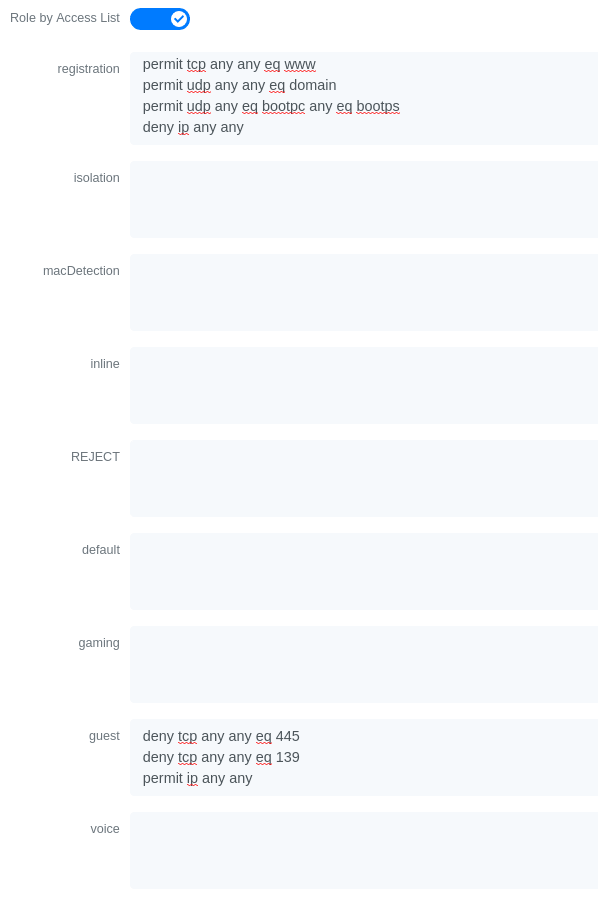
Or also could restrict the users to use only the DNS server where 192.168.5.2 is the DNS server
3.10.6. Cisco IOS 15.5
PortSecurity for IOS 12.2(46)SE or greater
Since version PacketFence 2.2.1, the way to handle VoIP when using port-security dramatically changed. Ensure that you follow the instructions below. To make the story short, instead on relying on the dynamic MAC learning for VoIP, we use a static entry on the voice VLAN so we can trigger a new security violation, and then authorize the phone MAC address on the network.
Global config settings:
snmp-server community public RO
snmp-server community private RW
snmp-server enable traps port-security
snmp-server enable traps port-security trap-rate 1
snmp-server host 192.168.1.5 version 2c public port-security
On each interface without VoIP:
switchport access vlan 4
switchport port-security
switchport port-security maximum 1 vlan access
switchport port-security violation restrict
switchport port-security mac-address 0200.000x.xxxx
where xxxxx stands for the interface ifIndex
On each interface with VoIP:
switchport voice vlan 100 switchport access vlan 4 switchport port-security switchport port-security maximum 2 switchport port-security maximum 1 vlan access switchport port-security maximum 1 vlan voice switchport port-security violation restrict switchport port-security mac-address 0200.010x.xxxx vlan voice switchport port-security mac-address 0200.000x.xxxx vlan access
where xxxxx stands for the interface ifIndex
Use the following templates for interface IfIndex in bogus MAC addresses
(0200.000x.xxxx):
- Fa0/1…Fa0/48 → 10001…10048
- Gi0/1…Gi0/48 → 10101…10148
2960, 2970, 3560, 3750
Make sure that you have a local account, because enabling 802.1X or MAB will ask for a username and password on the next login.
When doing 802.1X and network interface teaming on the same switch or stack, you might consider using the mac-move feature of the Cisco switches. When you authenticate the primary link of the team, the virtual MAC address will be published and authorized on the switchport. When something breaks on that link (ie. cable disconnected), the teaming driver will publish the MAC address on the secondary link, and the switch will try to authorize it. However, since the switch already has the MAC address in a session on another switchport, the switch will put the secondary link into err-disabled mode.
To prevent this behavior, you need to tell the switch to allow MAC address movements between ports. The global command is the following:
authentication mac-move permit
Global settings:
dot1x system-auth-controlaaa new-modelaaa group server radius packetfenceserver name pfnacaaa authentication login default localaaa authentication dot1x default group packetfenceaaa authorization network default group packetfence
RADIUS server configuration:
radius server pfnacaddress ipv4 192.168.1.5 auth-port 1812 acct-port 1813automate-tester username dummy ignore-acct-port idle-time 3key 0 useStrongerSecret
radius-server vsa send authentication
CoA configuration
aaa server radius dynamic-authorclient 192.168.1.5 server-key useStrongerSecretport 3799
Activate SNMP v1 on the switch:
snmp-server community public RO
802.1X with MAC Authentication bypass (MultiDomain)
On each interface:
switchport mode accessswitchport voice vlan 100authentication host-mode multi-domainauthentication order dot1x mabauthentication priority dot1x mabauthentication port-control autoauthentication periodicauthentication timer restart 10800authentication timer reauthenticate 10800authentication violation replacemabno snmp trap link-statusdot1x pae authenticatordot1x timeout quiet-period 2dot1x timeout tx-period 3
802.1X with MAC Authentication bypass (MultiHost)
On each interface:
switchport mode accessauthentication order dot1x mabauthentication priority dot1x mabauthentication port-control autoauthentication periodicauthentication timer restart 10800authentication timer reauthenticate 7200authentication violation replacemabno snmp trap link-statusdot1x pae authenticatordot1x timeout quiet-period 2dot1x timeout tx-period 3
MAC Authentication bypass only
On each interface:
switchport mode accessswitchport voice vlan 100dot1x mac-auth-bypassdot1x pae authenticatordot1x port-control autodot1x timeout tx-period 5dot1x reauthenticationauthentication periodicauthentication timer restart 10800authentication timer reauthenticate 7200authentication violation replacemabno snmp trap link-status
There’s a lot of different versions of the Catalyst 2960. Some of them may not accept the command stated in this guide for 802.1X.
We have found a couple of commands that are working great or MAB:
On each interface
switchport mode accessauthentication order mabauthentication port-control automabdot1x pae authenticator
But, as it is difficult for us to maintain the whole list of commands to configure each and every different model of 2960 with different IOS, please refer to Cisco documentation for very specific cases.
Web auth
The Catalyst 2960 supports web authentication from IOS 12.2.55SE3. This procedure has been tested on IOS 15.0.2SE5.
In this example, the ACL that triggers the redirection to the portal for registration is 'registration'.
Configure the global configuration of the switch using the section MAC Authentication bypass only of Cisco IOS 15.5 in this document.
Then add this additional configuration on the global level
ip device trackingip http serverip http secure-serversnmp-server community public ROsnmp-server community private RW
Add the required access lists
ip access-list extended registrationdeny ip any host <captive portal ip>permit tcp any any eq wwwpermit tcp any any eq 443
Then on each controlled interface
switchport access vlan <vlan>switchport mode accessauthentication priority mabauthentication port-control autoauthentication periodicauthentication violation replacemabspanning-tree portfast
PacketFence switch configuration
- Select the type to 'Cisco IOS 15.5'
- Set the 'Registration' role to 'registration' (If left empty then it will use the role name)
- Set Role by Web Auth URL for registration to 'http://<your_captive_portal_ip>/Cisco::Cisco_IOS_15_5'
- The URL can contain dynamic parameters, like the MAC address ($mac), the switch IP ($switch_ip), the username ($user_name).
- Screenshots of this configuration are available in the Cisco WLC section of this guide.
Dynamic ACLs
The Cisco IOS 15.5 supports RADIUS pushed ACLs which means that you can define the ACLs centrally in PacketFence without configuring them in the switches and their rules will be applied to the switch during the authentication.
These ACLs are defined by role like the VLANs which means you can define different ACLs for the registration VLAN, production VLAN, guest VLAN, etc.
Add the following configuration setting on the global level
ip device tracking
For IOS 12.2, you need to create this acl and assign it to the switch port interface:
ip access-list extended Auth-Default-ACLpermit udp any range bootps 65347 any range bootpc 65348permit udp any any range bootps 65347permit udp any any eq domaindeny ip any any
interface GigabitEthernetx/y/z...ip access-group Auth-Default-ACL in...
Before continuing, configure the switch to be in MAC authentication bypass or 802.1X.
Now in the PacketFence interface go in the switch configuration and in the Roles tab.
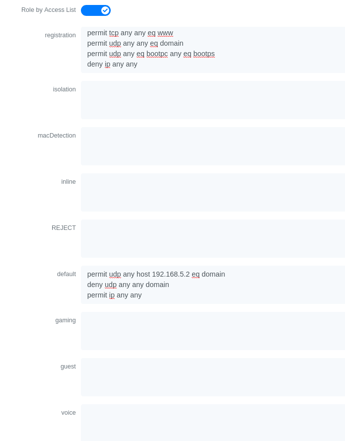
Check 'Role by access list' and you should now be able to configure the access lists as below.
For example if you want the users that are in the registration VLAN to only use HTTP, HTTPS, DNS and DHCP you can configure this ACL in the registration category.
Now if for example, the normal users are placed in the 'default' category and the guests in the 'guest' category.
If for example the 'default' category uses the network 192.168.5.0/24 and the guest network uses the network 192.168.10.0/24.
You can prevent communications between both networks using these access lists
Could also only prevent the guest users from using shared directories
Or also could restrict the users to use only the DNS server where 192.168.5.2 is the DNS server
Downloadable ACLs
Starting from IOS 15.2, Cisco switches supports Downloadable ACLs. The size of the radius packet limit the number of ACLs a switch can receive from a single Access-Accept answer, so Cisco Switches supports Downloadable ACLs which mean that the RADIUS server will do multiples Access-Challenge to send the complete ACL.
Use the Cisco::Cisco_IOS_15_5 switch module to use the DACLs method and use the same Global settings as the 'Dynamic ACLs' section above.
Add the following configuration setting on the global level
ip device tracking
Web auth and Dynamic ACLs
It’s possible to mix web authentication and downloadable ACLs starting from version 12.2 of the IOS, each roles can be configured to forward the device to the captive portal for an http or an https and only allow specific traffic with the ACL. To do that, you need to configure PacketFence with Role by Web Auth URL and with Role by access list (For each role you need). On the switch you need to change the Auth-Default-ACL to add the portal IP address:
For IOS 12.2:
ip access-list extended Auth-Default-ACLpermit udp any range bootps 65347 any range bootpc 65348permit udp any any range bootps 65347permit ip any host ip_of_the_captive_portalpermit udp any any eq domaindeny ip any any
And assign this ACL on the switch port yo want to do ACL per port.
interface GigabitEthernetx/y/z...ip access-group Auth-Default-ACL in...
For IOS 15.0:
Extended IP access list Auth-Default-ACL10 permit udp any range bootps 65347 any range bootpc 6534820 permit udp any any range bootps 6534730 deny ip any any
conf tip access-list extend Auth-Default-ACL21 permit ip any host ip_of_the_captive_portal
For IOS 15.2:
Extended IP access list Auth-Default-ACL10 permit udp any any eq domain20 permit tcp any any eq domain30 permit udp any eq bootps any40 permit udp any any eq bootpc50 permit udp any eq bootpc any60 deny ip any any
conf tip access-list extend Auth-Default-ACL51 permit ip any host ip_of_the_captive_portal
3.10.7. Stacked 29xx, Stacked 35xx, Stacked 3750, 4500 Series, 6500 Series
The 4500 Series and all the stacked switches work exactly the same way as if they were not stacked so the configuration is the same: they support port-security with static MAC address and allow us to secure a MAC on the data VLAN so we enable it whether there is VoIP or not.
We need to secure bogus MAC addresses on ports in order for the switch to send a trap when a new MAC appears on a port.
Global config settings
snmp-server community public ROsnmp-server community private RWsnmp-server enable traps port-securitysnmp-server enable traps port-security trap-rate 1snmp-server host 192.168.1.5 version 2c public port-security
On each interface without VoIP:
switchport access vlan 4switchport port-securityswitchport port-security maximum 1 vlan accessswitchport port-security violation restrictswitchport port-security mac-address 0200.000x.xxxx
On each interface with VoIP:
switchport voice vlan 100switchport access vlan 4switchport port-securityswitchport port-security maximum 2switchport port-security maximum 1 vlan accessswitchport port-security violation restrictswitchport port-security mac-address 0200.000x.xxxx
where xxxxx stands for the interface ifIndex
Use the following templates for interface IfIndex in bogus MAC addresses
(0200.000x.xxxx):
- Fa1/0/1…Fa1/0/48 → 10001…10048
- Gi1/0/1…Gi1/0/48 → 10101…10148
- Fa2/0/1…Fa2/0/48 → 10501…10548
- Gi2/0/1…Gi2/0/48 → 10601…10648
- Fa3/0/1…Fa3/0/48 → 11001…11048
- Gi3/0/1…Gi3/0/48 → 11101…11148
- Fa4/0/1…Fa4/0/48 → 11501…11548
- Gi4/0/1…Gi4/0/48 → 11601…11648
- …
3.10.8. IOS XE Switches
PacketFence supports the IOS XE switches in MAC Authentication Bypass, 802.1X and web authentication.
MAC Authentication Bypass
Global config settings:
dot1x system-auth-control
On each interface:
authentication host-mode multi-domainauthentication order mabauthentication priority mabauthentication port-control autoauthentication periodicauthentication timer restart 10800authentication timer reauthenticate 10800authentication violation replacemabno snmp trap link-statusdot1x pae authenticatordot1x timeout quiet-period 2dot1x timeout tx-period 3
AAA groups and configuration:
aaa new-modelaaa group server radius packetfenceserver 192.168.1.5 auth-port 1812 acct-port 1813aaa authentication login default localaaa authentication dot1x default group packetfenceaaa authorization network default group packetfence
RADIUS server configuration:
radius-server host 192.168.1.5 auth-port 1812 acct-port 1813 timeout 2 keyuseStrongerSecretradius-server vsa send authentication
CoA configuration:
aaa server radius dynamic-authorclient 192.168.1.5 server-key useStrongerSecretport 3799
Activate SNMP on the switch:
snmp-server community public RO
802.1X only
Follow the same configuration as for MAC Authentication Bypass but change the
authentication priority line with the following:
authentication priority dot1x
802.1X with MAC Authentication fallback
Follow the same configuration as for MAC Authentication Bypass but change the
authentication priority line with the following:
authentication priority dot1x mab
Web auth
Web auth requires at least MAC Authentication Bypass to be activated on the switchport but can also work with 802.1X. Configure your switchports as you would usually do, then add the following access lists.
ip access-list extended redirectdeny ip any host 192.168.1.5deny udp any any eq domaindeny tcp any any eq domaindeny udp any any eq bootpcdeny udp any any eq bootpspermit tcp any any eq wwwpermit tcp any any eq 443ip access-list extended registeredpermit ip any any
Global config settings:
ip device tracking
PacketFence switch configuration:
- Select the type to 'Cisco IOS 15.5'
- Set the 'Registration' role to 'registration' (If left empty then it will use the role name)
- Set Role by Web Auth URL for registration to 'http://<your_captive_portal_ip>/Cisco::Cisco_IOS_15_5'
- The URL can contain dynamic parameters, like the MAC address ($mac), the switch IP ($switch_ip), the username ($user_name).
- Screenshots of this configuration are available in the Cisco WLC section of this guide.
no aaa
accounting system default start-stop group tacacs+.Identity Networking Policy
Starting from version 15.2(1)E (IOS) and 3.4E (IOSXE) , Cisco introduced the Identity Based Networking Services. It means that you can create an authentication workflow on the switch and create interfaces templates.
To enable it:
authentication display new-style
Global config settings:
dot1x system-auth-control
AAA groups and configuration:
aaa new-modelaaa group server radius packetfenceserver name packetfence!aaa authentication login default localaaa authentication dot1x default group packetfenceaaa authorization network default group packetfenceradius-server vsa send authentication
RADIUS server configuration:
radius-server dead-criteria time 5 tries 4radius-server deadtime 1radius server packetfenceaddress ipv4 192.168.1.5 auth-port 1812 acct-port 1813key useStrongerSecretautomate-tester username cisco ignore-acct-port idle-time 1
CoA configuration:
aaa server radius dynamic-authorclient 192.168.1.5 server-key useStrongerSecretport 3799
Enable SNMP on the switch:
snmp-server community public RO
Enable HTTP and HTTPS server:
ip http serverip http secure-server
Enable IP device tracking:
ip device tracking
Fallback ACL:
ip access-list extended ACL-CRITICAL-V4permit ip any any
Service Template:
service-template DEFAULT_LINKSEC_POLICY_MUST_SECUREservice-template DEFAULT_LINKSEC_POLICY_SHOULD_SECUREservice-template DEFAULT_CRITICAL_VOICE_TEMPLATEvoice vlanservice-template CRITICAL_AUTH_VLANservice-template CRITICAL-ACCESSdescription *Fallback Policy on AAA Fail*access-group ACL-CRITICAL-V4!
Class map:
class-map type control subscriber match-any IN_CRITICAL_AUTHmatch activated-service-template DEFAULT_CRITICAL_VOICE_TEMPLATEmatch activated-service-template CRITICAL_AUTH_VLANmatch activated-service-template CRITICAL-ACCESS!class-map type control subscriber match-none NOT_IN_CRITICAL_AUTHmatch activated-service-template DEFAULT_CRITICAL_VOICE_TEMPLATEmatch activated-service-template CRITICAL_AUTH_VLANmatch activated-service-template CRITICAL-ACCESS!class-map type control subscriber match-all AAA_SVR_DOWN_UNAUTHD_HOSTmatch result-type aaa-timeoutmatch authorization-status unauthorized!class-map type control subscriber match-all AAA_SVR_DOWN_AUTHD_HOSTmatch result-type aaa-timeoutmatch authorization-status authorized!class-map type control subscriber match-all DOT1X_NO_RESPmatch method dot1xmatch result-type method dot1x agent-not-found!class-map type control subscriber match-all MAB_FAILEDmatch method mabmatch result-type method mab authoritative!class-map type control subscriber match-all DOT1X_FAILEDmatch method dot1xmatch result-type method dot1x authoritative
Policy map:
On the 3 following configurations if the RADIUS server is down then we will apply CRITICAL_AUTH_VLAN, DEFAULT_CRITICAL_VOICE_TEMPLATE and CRITICAL-ACCESS service template. If the RADIUS server goes up then it reinitializes the authentication if the port is in IN_CRITICAL_VLAN.
for 802.1X with MAC Authentication fallback:
policy-map type control subscriber DOT1X_MABevent session-started match-all10 class always do-until-failure10 authenticate using dot1x priority 10event authentication-failure match-first5 class DOT1X_FAILED do-until-failure10 terminate dot1x20 authenticate using mab priority 2010 class AAA_SVR_DOWN_UNAUTHD_HOST do-until-failure10 activate service-template CRITICAL_AUTH_VLAN20 activate service-template DEFAULT_CRITICAL_VOICE_TEMPLATE30 activate service-template CRITICAL-ACCESS40 authorize50 pause reauthentication20 class AAA_SVR_DOWN_AUTHD_HOST do-until-failure10 activate service-template CRITICAL_AUTH_VLAN20 activate service-template DEFAULT_CRITICAL_VOICE_TEMPLATE30 activate service-template CRITICAL-ACCESS40 pause reauthentication50 authorize30 class DOT1X_NO_RESP do-until-failure10 terminate dot1x20 authenticate using mab priority 2040 class MAB_FAILED do-until-failure10 terminate mab20 authentication-restart 1080060 class always do-until-failure10 terminate dot1x20 terminate mab30 authentication-restart 10800event agent-found match-all10 class always do-until-failure10 terminate mab20 authenticate using dot1x priority 10event aaa-available match-all10 class IN_CRITICAL_AUTH do-until-failure10 clear-session20 class NOT_IN_CRITICAL_AUTH do-until-failure10 resume reauthenticationevent inactivity-timeout match-all10 class always do-until-failure10 clear-sessionevent authentication-success match-all10 class always do-until-failure10 activate service-template DEFAULT_LINKSEC_POLICY_SHOULD_SECUREevent violation match-all10 class always do-all10 replace
for MAC Authentication only:
policy-map type control subscriber MACAUTHevent session-started match-all10 class always do-until-failure10 authenticate using mab priority 10event authentication-failure match-first10 class AAA_SVR_DOWN_UNAUTHD_HOST do-until-failure10 activate service-template CRITICAL_AUTH_VLAN20 activate service-template DEFAULT_CRITICAL_VOICE_TEMPLATE30 activate service-template CRITICAL-ACCESS40 authorize50 pause reauthentication20 class AAA_SVR_DOWN_AUTHD_HOST do-until-failure10 activate service-template CRITICAL_AUTH_VLAN20 activate service-template DEFAULT_CRITICAL_VOICE_TEMPLATE30 activate service-template CRITICAL-ACCESS40 pause reauthentication50 authorize30 class always do-until-failure10 terminate mab20 authentication-restart 30event aaa-available match-all10 class IN_CRITICAL_AUTH do-until-failure10 clear-session20 class NOT_IN_CRITICAL_AUTH do-until-failure10 resume reauthenticationevent inactivity-timeout match-all10 class always do-until-failure10 clear-sessionevent authentication-success match-all10 class always do-until-failure10 activate service-template DEFAULT_LINKSEC_POLICY_SHOULD_SECURE
for 802.1X only:
policy-map type control subscriber DOT1Xevent session-started match-all10 class always do-until-failure10 authenticate using dot1x priority 10event authentication-failure match-first10 class AAA_SVR_DOWN_UNAUTHD_HOST do-until-failure10 activate service-template CRITICAL_AUTH_VLAN20 activate service-template DEFAULT_CRITICAL_VOICE_TEMPLATE30 activate service-template CRITICAL-ACCESS40 authorize50 pause reauthentication20 class AAA_SVR_DOWN_AUTHD_HOST do-until-failure10 activate service-template CRITICAL_AUTH_VLAN20 activate service-template DEFAULT_CRITICAL_VOICE_TEMPLATE30 activate service-template CRITICAL-ACCESS40 pause reauthentication50 authorize30 class DOT1X_FAILED do-until-failure10 terminate dot1x40 class DOT1X_NO_RESP do-until-failure10 terminate dot1x60 class always do-until-failure10 terminate dot1x20 authentication-restart 10800event agent-found match-all10 class always do-until-failure10 authenticate using dot1x priority 10event aaa-available match-all10 class IN_CRITICAL_AUTH do-until-failure10 clear-session20 class NOT_IN_CRITICAL_AUTH do-until-failure10 resume reauthenticationevent inactivity-timeout match-all10 class always do-until-failure10 clear-sessionevent authentication-success match-all10 class always do-until-failure10 activate service-template DEFAULT_LINKSEC_POLICY_SHOULD_SECURE
Interface Template (802.1X MAC Authentication):
template identity-template-mabdot1x pae authenticatorspanning-tree portfast edgeswitchport access vlan 1switchport mode accessswitchport voice vlan 100mabaccess-session host-mode multi-domainaccess-session control-direction inaccess-session closedaccess-session port-control autoauthentication periodicauthentication timer reauthenticate serverservice-policy type control subscriber DOT1X_MAB
Interface Template (MAC Authentication):
template identity-template-macauthdot1x pae authenticatorspanning-tree portfast edgeswitchport access vlan 1switchport mode accessswitchport voice vlan 100mabaccess-session host-mode single-hostaccess-session control-direction inaccess-session closedaccess-session port-control autoauthentication periodicauthentication timer reauthenticate serverservice-policy type control subscriber MACAUTH
Interface Template (802.1X):
template identity-template-dot1xdot1x pae authenticatorspanning-tree portfast edgeswitchport access vlan 1switchport mode accessswitchport voice vlan 100mabaccess-session host-mode single-hostaccess-session control-direction inaccess-session closedaccess-session port-control autoauthentication periodicauthentication timer reauthenticate serverservice-policy type control subscriber DOT1X
On each interface for 802.1X with MAC Authentication:
source template identity-template-mabdot1x timeout tx-period 5
On each interface for MAC Authentication:
source template identity-template-macauth
On each interface for 802.1X:
source template identity-template-dot1xdot1x timeout tx-period 5
To see what is the status of a port let’s run:
sh access-session interface fastEthernet 0/2 detailsInterface: FastEthernet0/2MAC Address: 101f.74b2.f6a5IPv6 Address: UnknownIPv4 Address: 172.20.20.49User-Name: ACME\bobStatus: AuthorizedDomain: DATAOper host mode: multi-domainOper control dir: inSession timeout: 12380s (server), Remaining: 12206sTimeout action: TerminateCommon Session ID: AC1487290000000C000F8B7AAcct Session ID: UnknownHandle: 0x9C000001Current Policy: DOT1X_MAB
Local Policies:Service Template: DEFAULT_LINKSEC_POLICY_SHOULD_SECURE (priority 150)
Server Policies:Vlan Group: Vlan: 20Idle timeout: 30 sec
Method status list:Method State
dot1x Authc Success
Debug command:
In order to be able to debug the Identity Networking Policy you can launch the following command in the switch cli:
term mondebug pre all
DHCP Option 82
In order to enable the DHCP Option 82, you need to add the following parameters. Let’s say you want to enable it for the vlan 1 to 1024:
ip dhcp snoopingip dhcp snooping vlan 1-1024
On uplink interfaces:
ip dhcp snooping trust
Router ISR 1800 Series
PacketFence supports the 1800 series Router with linkUp / linkDown traps. It
cannot do
anything about the router interfaces (ie: fa0 and fa1 on a 1811). VLAN
interfaces ifIndex should
also be marked as uplinks in the PacketFence switch configuration as they
generate traps but
are of no interest to PacketFence (layer 3).
Global config settings:
snmp-server enable traps snmp linkdown linkupsnmp-server host 192.168.1.5 trap version 2c public
On each interface:
switchport mode accessswitchport access vlan 4
3.10.9. EAP-FAST authentication Support
PacketFence supports Cisco NEAT through EAP-MD5, EAP-FAST, EAP-GTC and EAP-MSCHAPv2 authentication methods. Upon successful authentication against PacketFence, the authenticator switch will give trunk access to the supplicant switch.
Here is an official Cisco guide, from which the following configuration derives: https://www.cisco.com/c/en/us/support/docs/lan-switching/8021x/116681-config-neat-cise-00.html
The following configuration example contains required changes to be applied on both authenticator and supplicant switches to provide EAP-FAST authentication against PacketFence.
Authenticator
Global settings:
aaa group server radius packetfenceserver 192.168.1.5 auth-port 1812 acct-port 1813aaa authentication dot1x default group packetfenceaaa authorization network default group packetfence
cisp enable
Uplink configuration:
interface FastEthernet0/20switchport mode accessauthentication port-control autodot1x pae authenticator
Supplicant
Global settings (replace username and password):
cisp enable
eap profile EAP_PROmethod fast
dot1x credentials EAP_PROusername switchespassword 7 03174C02120C29495D! Password is switches!dot1x supplicant force-multicast
Uplink settings:
interface GigabitEthernet1/0/24switchport mode trunkdot1x pae supplicantdot1x credentials EAP_PROdot1x supplicant eap profile EAP_PRO
3.10.10. Device Sensor for Cisco Equipment
Device sensor is a way to be able to receive some information about endpoints from the RADIUS accounting packet. (like DHCP, CDP, LLDP and HTTP information) In order to enable Device Sensor feature, you need to add the following parameters to your switch configuration:
radius server packetfenceaddress ipv4 192.168.1.5 auth-port 1812 acct-port 1813key useStrongerSecret
aaa group server radius packetfenceserver name packetfence!aaa accounting update newinfoaaa accounting identity default start-stop group packetfence!!device-sensor filter-list dhcp list dhcp-listoption name host-nameoption name parameter-request-listoption name class-identifier!device-sensor filter-list lldp list lldp-listtlv name system-description!device-sensor filter-list cdp list cdp-listtlv name version-typetlv name platform-type!device-sensor filter-list dhcp list lldp-listdevice-sensor filter-spec dhcp include list dhcp-listdevice-sensor filter-spec lldp include list lldp-listdevice-sensor filter-spec cdp include list cdp-listdevice-sensor notify all-changes
This configuration will make the switch send information about DHCP, LLDP and CDP of the endpoint in the RADIUS accounting packets.
3.11. Cisco Small Business (SMB)
Cisco Small Business switches support MAC authentication (MAB), 802.1X, and VoIP. Both technologies can be combined on the same switchport.
VoIP activation requires no switch configuration; configure voice VLAN in PacketFence switch configuration and enable VoIP there. Phones must send untagged traffic when connected to PacketFence-enabled ports. Do not enable voice VLAN capabilities on switch as they may conflict with PacketFence authorization attributes.
3.11.1. Global configuration
Define RADIUS server pointing to PacketFence:
dot1x system-auth-controlradius-server key useStrongerSecretradius-server host 192.168.1.5
aaa accounting dot1x start-stop group radius
snmp-server community public ro view Defaultsnmp-server community private rw view Default
SNMP configuration for the Cisco SG300:
snmp-server community public ro view DefaultSupersnmp-server community private rw view DefaultSuper
3.11.2. MAC Authentication
Configure MAC authentication on each interface:
interface x/y/zdot1x host-mode multi-sessionsdot1x reauthenticationdot1x timeout reauth-period 10800dot1x timeout quiet-period 10dot1x timeout server-timeout 5dot1x timeout supp-timeout 3dot1x authentication macdot1x radius-attributes vlandot1x port-control autospanning-tree portfastswitchport mode generalswitchport general pvid 2
3.11.3. 802.1X with MAB
Configure 802.1X with MAC authentication fallback on each interface:
interface x/y/zdot1x host-mode multi-sessionsdot1x reauthenticationdot1x timeout quiet-period 10dot1x timeout server-timeout 5dot1x timeout supp-timeout 3dot1x authentication dot1x macdot1x radius-attributes vlandot1x port-control autospanning-tree portfastswitchport mode generalswitchport general pvid 2
Configure switch in PacketFence with following information:
-
Definition → Type:
Cisco SG500 -
Definition → Mode:
production -
Definition → Deauthentication Method:
SNMP - Definition → VoIP enabled if you need VoIP on this switch.
- Roles → voice VLAN set to the VLAN you want to assign to the VoIP devices connecting to this switch.
-
RADIUS → Secret Passphrase:
useStrongerSecret -
SNMP → Version:
v2c -
SNMP → Community Read:
public -
SNMP → Community Write:
private
3.11.4. 802.1X commands
show dot1xshow dot1x users
3.12. D-Link
PacketFence supports D-Link switches without VoIP using two different trap types:
- linkUp/linkDown
- MAC Notification
We recommend to enable linkUp/linkDown and MAC notification together.
Don’t forget to update the startup config!
3.12.1. DES3526 / 3550
Global config settings
To be contributed...
On each interface:
To be contributed...
3.12.2. DGS3100/3200
Enable MAC notification:
enable mac_notificationconfig mac_notification interval 1 historysize 1config mac_notification ports 1:1-1:24 enable
Enable linkup/linkdown notification:
enable snmp trapsenable snmp linkchange_traps
Add SNMP host:
create snmp host 192.168.1.5 v2c public
Enable MAC base access control:
enable mac_based_access_controlconfig mac_based_access_control authorization attributes radius enable local disableconfig mac_based_access_control method radiusconfig mac_based_access_control password useStrongerSecretconfig mac_based_access_control password_type manual_stringconfig mac_based_access_control max_users no_limitconfig mac_based_access_control trap state enableconfig mac_based_access_control log state enable
On each interface:
config mac_based_access_control ports 1:1 state enableconfig mac_based_access_control ports 1:1 max_users 128config mac_based_access_control ports 1:1 aging_time 1440config mac_based_access_control ports 1:1 block_time 300config mac_based_access_control ports 1:1 mode host_based
3.13. Dell
3.13.1. Force 10
PacketFence supports this switch using RADIUS, MAC-Authentication and 802.1X.
Global config settings
radius-server host 192.168.1.5 key s3cr3t auth-port 1812
MAB interface configuration:
interface GigabitEthernet 0/1no ip addressswitchportdot1x authenticationdot1x mac-auth-bypassdot1x auth-type mab-onlyno shutdown
802.1X interface configuration:
interface GigabitEthernet 0/1no ip addressswitchportdot1x authenticationno shutdown
3.13.2. PowerConnect 3424
PacketFence supports this switch using linkUp/linkDown traps.
Global config settings to define the RADIUS server
configureradius-server host auth 10.34.200.30name PacketFenceusage 802.1xkey s3cr3texit
Configure CoA
aaa server radius dynamic-authorclient 10.34.200.30 server-key s3cr3tauth-type allexit
Enable authentication and globally enable 802.1x client authentication via RADIUS
authentication enableaaa authentication dot1x default radiusaaa authorization network default radiusdot1x system-auth-control
(Optional)
dot1x dynamic-vlan enable
On the interface, enable MAC based authentication mode, enable MAB, and set the order of authentication to 802.1X followed by MAC authentication. Also enable periodic re-authentication.
interface te1/0/4dot1x port-control mac-baseddot1x mac-auth-bypassauthentication order dot1x mabdot1x reauthenticationdefault mab papexit
authentication order mabauthentication priority mab
3.13.3. N1500 Series Switch
PacketFence supports this switch using RADIUS, MAC-Authentication, 802.1x and VoIP
802.1X with MAC Authentication fallback and VoIP
We assume that the switch ip is 192.168.1.254
First on the uplink add this configuration:
dot1x port-control force-authorizedswitchport mode trunkswitchport trunk allowed vlan 1-5,100
Global config settings
configurevlan 2,3,4,5,100vlan 2name "Registration"vlan 3name "Isolation"vlan 4name "Mac detection"vlan 5name "Guest"vlan 100name "VoIP"
authentication enabledot1x system-auth-controlaaa authentication dot1x default radiusaaa authorization network default radiusradius server vsa send authenticationdot1x dynamic-vlan enablevoice vlanaaa server radius dynamic-authorclient 192.168.1.5 server-key "useStrongerSecret"exitradius-server host auth 192.168.1.5name "PacketFence"usage 802.1xkey "useStrongerSecret"exitaaa server radius dynamic-authorclient 192.168.1.5 server-key "useStrongerSecret"exit
snmp-server community "private" rwsnmp-server community "public" ro
On each interface (not uplink)
switchport voice detect autoswitchport mode generalswitchport access vlan 10dot1x port-control mac-baseddot1x reauthenticationdot1x mac-auth-bypassauthentication order mabauthentication priority mablldp transmit-tlv sys-desc sys-caplldp transmit-mgmtlldp notificationlldp med confignotificationvoice vlan 100exit
3.13.4. N1500 Series (FW >= 6.6.0.17)
This configuration has been tested with firmware 6.6.0.17
Global config settings:
aaa authentication login "defaultList" localauthentication enableauthentication dynamic-vlan enabledot1x system-auth-controlaaa authentication dot1x default radiusaaa authorization network default radiusaaa accounting dot1x default start-stop radiusip device trackingauthentication dynamic-vlan enableradius server auth 192.168.1.5key useStrongerSecretusage authmgrname "PacketFence"exitradius server acct 192.168.1.5name "PacketFenceAccounting"key useStrongerSecretexitsnmp-server community "private" rwsnmp-server community "public" ro
802.1X/MAB with VoIP interface configuration:
switchport voice detect autoswitchport mode generalswitchport general pvid 2switchport general allowed vlan add 1-4093authentication host-mode multi-domainauthentication periodicdot1x timeout quiet-period 10mab auth-type papauthentication order mabno authentication allow-unauth dhcplldp tlv-select system-description system-capabilities management-addresslldp notificationlldp med confignotificationswitchport voice vlan 100
Uplink port:
switchport mode trunkswitchport trunk allowed vlan 1-4096authentication port-control force-authorized
On other switch ports not managed by PacketFence:
switchport mode generalswitchport general pvid xswitchport general allowed vlan add xauthentication port-control force-authorized
Web-Auth:
ip access-list registration1000 deny ip any 192.168.1.5 0.0.0.01010 permit tcp any any eq http1020 permit tcp any any eq 443
3.13.5. N1500 Series (FW >= 6.8)
Downloadable ACLs:
This configuration has been tested on FW 6.8.1. Important, even if "authentication allow-srcipanyacl enable" has been enable on the switch, it doesn’t support ACL with source ip and the ACL direction are only in. So, for example, if you have this configured in PacketFence:
permit ip 10.0.0.1 host 192.168.3.1permit ip any any
Then you have to convert it to:
permit ip any host 192.168.3.1permit ip any any
The configuration needs to be done is the one above (N1500 Series (FW >= 6.6.0.17))
Troubleshooting command:
debug consoledebug authentication event Gigabitethernet 1/0/1terminal monitorshow authentication clients gigabitethernet 1/0/1
3.13.6. N2000 Series (N2024P)
This configuration was tested with firmware version 6.2.1.6
Global config settings:
Radius configuration:
aaa authentication login "defaultList" localauthentication enabledot1x system-auth-controlaaa authentication dot1x default radiusaaa authorization network default radiusdot1x dynamic-vlan enableradius-server key "useStrongerSecret"radius-server host auth 192.168.1.5name "PacketFence"
802.1X interface configuration:
interface Gi0/0/1switchport mode generalswitchport general allowed vlan add 1-3,100dot1x port-control mac-baseddot1x unauth-vlan 2dot1x mac-auth-bypassauthentication order mab dot1xvoice vlan 100exit
3.14. Edge core
PacketFence supports Edge-corE switches without VoIP using linkUp/linkDown traps.
PacketFence also supports MAC authentication on the Edge-corE 4510
3.14.1. 3526XA and 3528M
Global config settings
SNMP-server host 192.168.1.5 public version 2c udp-port 162
3.14.2. 4510
Basic configuration
network-access agingsnmp-server community private rwsnmp-server community public rwradius-server 1 host 192.168.1.5 auth-port 1812 acct-port 1813 timeout 5 retransmit 2 key useStrongerSecretradius-server key useStrongerSecret
On each controlled interface
interface ethernet 1/8switchport allowed vlan add <your list of allowed vlans> untaggednetwork-access max-mac-count 1network-access mode mac-authentication!
3.15. Enterasys
PacketFence supports Enterasys switches without VoIP using two different trap types:
- linkUp/linkDown
- MAC Locking (Port Security with static MACs)
We recommend to enable MAC locking only.
Don’t forget to update the startup config!
3.15.1. Matrix N3
linkUp/linkDown traps are enabled by default so we disable them and enable MAC
locking
only. Also, by default this switch doesn’t do an electrical low-level linkDown
when setting the
port to admin down. So we need to activate a global option called
forcelinkdown to enable
this behavior. Without this option, clients don’t understand that they lost
their connection and
they never do a new DHCP on VLAN change.
Global config settings
set snmp community publicset snmp targetparams v2cPF user public security-model v2c message-processing v2cset snmp notify entryPF tag TrapPFset snmp targetaddr tr 192.168.1.5 param v2cPF taglist TrapPFset maclock enableset forcelinkdown enable
On each interface:
set port trap ge.1.xx disableset maclock enable ge.1.xxset maclock static ge.1.xx 1set maclock firstarrival ge.1.xx 0set maclock trap ge.1.xx enable
where xx stands for the interface index.
3.15.2. SecureStack C2
linkUp/linkDown traps are enabled by default so we disable them and enable MAC locking only.
Global config settings
set snmp community publicset snmp targetparams v2cPF user public security-model v2c message-processing v2cset snmp notify entryPF tag TrapPFset snmp targetaddr tr 192.168.1.5 param v2cPF taglist TrapPFset maclock enable
On each interface:
set port trap fe.1.xx disableset maclock enable fe.1.xxset maclock static fe.1.xx 1set maclock firstarrival fe.1.xx 0
where xx stands for the interface index
3.15.3. SecureStack C3
This switch has the particular feature of allowing more than one untagged egress VLAN per port. This means that you must add all the VLAN created for PacketFence as untagged egress VLAN on the relevant interfaces. This is why there is a VLAN command on each interface below.
linkUp/linkDown traps are enabled by default so we disable them and enable MAC locking only.
Global config settings
set snmp community publicset snmp targetparams v2cPF user public security-model v2c message-processing v2cset snmp notify entryPF tag TrapPFset snmp targetaddr tr 192.168.1.5 param v2cPF taglist TrapPFset maclock enable
On each interface:
set vlan egress 1,2,3 ge.1.xx untaggedset port trap ge.1.xx disableset maclock enable ge.1.xxset maclock static ge.1.xx 1set maclock firstarrival ge.1.xx 0set maclock trap ge.1.xx enable
where xx stands for the interface index
3.15.4. Standalone D2
linkUp/linkDown traps are enabled by default so we disable them and enable MAC locking only.
clear vlan egress <vlans> <ports>Global config settings
set snmp community publicset snmp targetparams v2cPF user public security-model v2c message-processing v2cset snmp notify entryPF tag TrapPFset snmp targetaddr tr 192.168.1.5 param v2cPF taglist TrapPFset maclock enable
On each interface:
set port trap ge.1.xx disableset maclock enable ge.1.xxset maclock static ge.1.xx 1set maclock firstarrival ge.1.xx 0set maclock trap ge.1.xx enable
where xx stands for the interface index
3.16. Extreme Networks
PacketFence supports Extreme Networks switches using:
- linkUp/linkDown
- MAC Address Lockdown (Port Security)
- Netlogin - MAC Authentication
- Netlogin - 802.1X
- Netlogin - web authentication
- RADIUS authentication for CLI access
Don’t forget to save the configuration!
3.16.1. All Extreme XOS based switches
In addition to the SNMP and VLANs settings, this switch needs the Web Services to be enabled and an administrative username and password provided in its PacketFence configuration for Web Services.
3.16.2. Extreme EXOS v30.x
This switch version module is designed for Extreme switch series utilizing Extreme versions v30.x Note: "EXOS v30.x" module is tailored for the switch series operating on Extreme versions v30.x. Furthermore, it inherits all functionalities from the existing "EXOS" module, making all the configurations below applicable to EXOS v30.x.
MAC Address Lockdown (Port-Security)
linkUp/linkDown traps are enabled by default so we disable them and enable MAC Address Lockdown only.
Global config settings without Voice over IP (VoIP):
enable snmp accessconfigure snmp add trapreceiver 192.168.1.5 community publicenable web httpconfigure vlan "Default" delete ports <portlist>configure vlan registration add ports <portlist> untaggedconfigure ports <portlist> vlan registration lock-learningdisable snmp traps port-up-down ports <portlist>
<portlist> = ports to secure (individual port or port-range with dash).
Global config settings with Voice over IP (VoIP):
enable snmp accessconfigure snmp add trapreceiver 192.168.1.5 community publicenable web httpconfigure vlan "Default" delete ports <portlist>configure vlan registration add ports <portlist> untaggedconfigure vlan voice add ports <portlist> taggedconfigure ports <portlist> vlan registration lock-learningconfigure ports <portlist> vlan voice limit-learning 1disable snmp traps port-up-down ports <portlist>
<portlist> = ports to secure (individual port or port-range with dash).
CoA configuration
Starting from version EXOS 22.1 CoA is supported.
configure radius dynamic-authorization 1 server 192.168.1.5 client-ip 10.0.0.8 vr VR-Default shared-secret useStrongerSecretenable radius dynamic-authorization
MAC Authentication
SNMP configuration
enable snmp access snmp-v1v2cconfigure snmp add community readonly publicconfigure snmp add community readwrite private
AAA Configuration
configure radius netlogin primary server 192.168.1.5 1812 client-ip 10.0.0.8 vr VR-Defaultconfigure radius netlogin primary shared-secret useStrongerSecretenable radius netlogin
Netlogin (MAC Authentication)
configure netlogin vlan tempenable netlogin macconfigure netlogin add mac-list defaultconfigure netlogin dynamic-vlan enableconfigure netlogin dynamic-vlan uplink-ports 50configure netlogin mac authentication database-order radiusenable netlogin ports 1-48 macconfigure netlogin ports 1-48 mode port-based-vlansconfigure netlogin ports 1-48 no-restart
802.1X
SNMP configuration
enable snmp access snmp-v1v2cconfigure snmp add community readonly publicconfigure snmp add community readwrite private
AAA Configuration
configure radius netlogin primary server 192.168.1.5 1812 client-ip 10.0.0.8 vr VR-Defaultconfigure radius netlogin primary shared-secret useStrongerSecretenable radius netlogin
Netlogin (802.1X)
configure netlogin vlan tempenable netlogin dot1xconfigure netlogin dynamic-vlan enableconfigure netlogin dynamic-vlan uplink-ports 50enable netlogin ports 1-48 dot1xconfigure netlogin ports 1-48 mode port-based-vlansconfigure netlogin ports 1-48 no-restartconfigure netlogin mac ports 1-48 timers reauth-period 86400 reauthentication onconfigure netlogin dot1x ports 1-48 timers server-timeout 10 reauth-period 84600
3.16.3. MAC Authentication + 802.1x
You can mix the MAC Authentication and 802.1X on the same switchport. If the device fails 802.1X authentication, it will fallback to the MAC Authentication. Configure the MAC Authentication and 802.1x like the section above and add this extra command:
enable netlogin ports 1-48 dot1x mac
Policy based access
Assign switch-defined policies via PacketFence.
Define switch policy:
configure policy profile 1 name "gaming" pvid-status "enable" pvid 3521 untagged-vlans 3521configure policy profile 2 name "guest" pvid-status "enable" pvid 3522 untagged-vlans 3522configure policy maptable response bothconfigure policy vlanauthorization enable
Enable 'Role by Switch Role' in PacketFence switch configuration; assign policies to roles. Policies returned in Filter-Id attribute.
Use 'Extreme EXOS' switch type for this feature.
Web authentication
SNMP configuration
enable snmp access snmp-v1v2cconfigure snmp add community readonly publicconfigure snmp add community readwrite private
AAA Configuration
configure radius netlogin primary server 192.168.1.5 1812 client-ip 10.0.0.8 vr VR-Defaultconfigure radius netlogin primary shared-secret useStrongerSecretenable radius netlogin
Web-auth profile
configure dns-client add name-server 8.8.8.8 vr VR-Mgmtconfigure dns-client add domain-suffix example.comconfigure policy captive-portal web-redirect 1 server 1 url http://192.168.1.5:80/Extreme::EXOS enableconfigure policy profile 4 name "Unregistered" pvid-status "enable" pvid 0 web-redirect 1configure policy rule 4 ipdestsocket 192.168.1.5 mask 32 forwardconfigure policy rule 4 udpdestportIP 53 mask 16 forwardconfigure policy rule 4 udpdestportIP 67 mask 16 forwardconfigure policy rule 4 ether 0x0806 mask 16 forwardconfigure policy captive-portal listening 80configure policy captive-portal listening 443
Enable 'External Portal Enforcement' and 'Role by Switch Role' in PacketFence switch configuration. Set 'registration' role to 'Unregistered'.
Use 'Extreme EXOS' switch type for this feature.
RADIUS authentication for CLI access
Configure RADIUS server IP as primary server and switch IP as client-ip. Specify correct virtual router:
configure radius mgmt-access primary server <SERVER_IP> 1815 client-ip <CLIENT_IP> vr <VR>
Configure the RADIUS shared-secret
configure radius mgmt-access primary shared-secret <SHARED_SECRET>
Enable RADIUS for management access
enable radius mgmt-access
3.17. Fortinet FortiSwitch
This section shows how to configure RADIUS, MAC Authentication, and 802.1X on a FortiSwitch running FortiSwitchOS 7.x.
CLI access to the FortiSwitch is required for this configuration.
3.17.1. RADIUS
Define an IPv4 RADIUS server using the CLI:
config user radiusedit <name>set addr-mode ipv4set server <IPv4_address>set source-ip <ipv4_address>set radius-port <radius_port_num>set secret <server_password>set auth-type {auto | chap | ms_chap | ms_chap_v2 | pap}set nas-ip <IPv4_address>set all-usergroup {enable | disable}set link-monitor {enable | disable}set link-monitor-interval <5-120 seconds>endend
3.17.2. Port Security Global Settings
Using the CLI:
config switch globalconfig port-securityset link-down-auth {no-action | set-unauth}set mab-reauth {enable | disable}set max-reauth-attempt <0-15>set reauth-period <0-1440>end
3.17.3. MAB
FortiSwitchOS 7.2.3+ supports MAB-only authentication. In this mode, the FortiSwitch performs MAB authentication without EAP authentication. EAP packets are not sent. Enable MAB-only authentication:
Switch Interface Configuration
config switch interfaceedit interface_nameconfig port-securityset port-security-mode {802.1X | 802.1X-mac-based}set mac-auth-bypass enableset auth-order MABendnextend
3.17.4. 802.1X
FortiSwitchOS 7.0+ supports 802.1X client mobility between ports without deleting the 802.1X session. For example, an 802.1X client PC connected through an IP phone to port1 can move to a third-party switch connected to port2 without session deletion.
This feature is available for 802.1X port-based authentication, 802.1X MAC-based authentication, MAB enabled or disabled, and EAP pass-through mode enabled or disabled.
Switch Interface Configuration
Configure 802.1X settings on an interface:
Using the CLI (for FSR-124D, 200 Series, FS-4xxE, 500 Series, FS-1024D, FS-1024E, FS-T1024E, FS-1048E, and FS-3032E):
config switch interfaceedit <port>config port-securityset allow-mac-move-to {disable | enable}set eap-egress-tagged {disable | enable}set port-security-mode {none | 802.1X | 802.1X-mac-based}set framevid-apply {disable | enable}set auth-fail-vlan {enable | disable}set auth-fail-vlanid <vlanid>set auth-priority {MAB-dot1x | dot1x-MAB | legacy}set authserver-timeout-period <3-15>set authserver-timeout-vlan {enable | disable}set authserver-timeout-vlanid <1-4094>set eap-passthru {enable | disable}set guest-auth-delay <integer>set guest-vlan {enable | disable}set guest-vlanid <vlanid>set mac-auth-bypass {enable | disable}set open-auth {enable | disable}set radius-timeout-overwrite {enable | disable}endset security-groups <security-group-name>end
Using the CLI (for FS-124F, FS-124F-POE, FS-124F-FPOE, FS-148F, FS-148F-POE, and FS-148F-FPOE):
config switch globalconfig port-securityset allow-mac-move {disable | enable}endend
config switch interfaceedit <port>config port-securityset eap-egress-tagged {disable | enable}set port-security-mode {none | 802.1X | 802.1X-mac-based}set framevid-apply {disable | enable}set auth-fail-vlan {enable | disable}set auth-fail-vlanid <vlanid>set auth-priority {MAB-dot1x | dot1x-MAB | legacy}set authserver-timeout-period <3-15>set authserver-timeout-vlan {enable | disable}set authserver-timeout-vlanid <1-4094>set eap-passthru {enable | disable}set guest-auth-delay <integer>set guest-vlan {enable | disable}set guest-vlanid <vlanid>set mac-auth-bypass {enable | disable}set open-auth {enable | disable}set radius-timeout-overwrite {enable | disable}endset security-groups <security-group-name>end
3.17.5. Dynamic ACL
FortiSwitchOS 7.x supports Dynamic Access Control Lists (DACL) which allow PacketFence to push ACL rules to the switch via RADIUS during authentication.
RADIUS Server and Security Group
First, ensure a RADIUS server is configured and associated with a security group:
config user radiusedit "<radius_server_name>"set auth-type ms_chap_v2set nas-ip <switch_ip_address>set secret <shared_secret>set server <packetfence_ip_address>nextend
config user groupedit "RadiusGroup1"set member "<radius_server_name>"nextend
Switch Interface Configuration
Enable DACL on the interface:
config switch interfaceedit <port>config port-securityset dacl enableset port-security-mode {802.1X | 802.1X-mac-based}set mac-auth-bypass enableendnextend
Complete example with all recommended settings:
config switch interfaceedit "port2"set security-groups "RadiusGroup1"set snmp-index 2config port-securityset allow-mac-move enableset auth-fail-vlan disableset auth-order MAB-dot1xset auth-priority legacyset authserver-timeout-period 3set authserver-timeout-tagged disableset authserver-timeout-vlan disableset client-limit 20set dacl enableset eap-auto-untagged-vlans enableset eap-egress-tagged enableset eap-passthru enableset framevid-apply enableset guest-auth-delay 5set guest-vlan disableset mab-eapol-request 3set mac-auth-bypass enableset open-auth disableset port-security-mode 802.1X-mac-basedset quarantine-vlan enableset radius-timeout-overwrite disableset auth-fail-vlanid 200set authserver-timeout-vlanid 300set guest-vlanid 100endnextend
PacketFence Configuration
On the PacketFence side, configure the switch to use ACL-based enforcement:
-
Navigate to Configuration → Policies and Access Control → Switches
-
Edit your FortiSwitch configuration
-
In the Roles section, enable "Role by Access List"
-
Define ACL rules for each role
Example ACL for a registration role (allows access to captive portal):
permit udp any any eq 53permit udp any any eq 67permit tcp any host 192.168.1.5 eq 80permit tcp any host 192.168.1.5 eq 443deny ip any any
When DACL is enabled, the switch diagnostic output will show:
Dynamic Access Control List : Enable
Viewing 802.1X Details
Show diagnostics for one or all ports using the CLI:
diagnose switch 802-1x status [<port>]
For example:
diagnose switch 802-1x status port3
port3: Mode: mac-based (mac-by-pass enable)Link: Link upPort State: authorized: ( )Dynamic Allowed Vlan list: 101Dynamic Untagged Vlan list: 101EAP pass-through : EnableAuth Order : MAB-dot1xAuth Priority : LegacyEAP egress-frame-tagged : EnableEAP auto-untagged-vlans : EnableAllow MAC Move : DisableDynamic Access Control List : DisableQuarantine VLAN (4093) detection : EnableNative Vlan : 101Allowed Vlan list: 1-200Untagged Vlan list: 101Guest VLAN :Auth-Fail Vlan :AuthServer-Timeout Vlan :
Switch sessions 1/240, Local port sessions:1/20Client MAC Type Traffic-Vlan Dynamic-Vlanf0:4d:a2:be:a3:31 802.1x 101 101
Sessions info:f0:4d:a2:be:a3:31 Type=802.1x,TTLS,state=AUTHENTICATED,etime=0,eap_cnt=9params:reAuth=60user="local-RADIUS",security_grp="radiusgrp",fortinet_grp="Radius_Admins"
Viewing Dynamic ACLs on a Port
Show the dynamic ACLs (DACL) applied to a port using the CLI:
diagnose switch 802-1x status-dacl <port>
For example:
diagnose switch 802-1x status-dacl port2
Clearing Authorized Sessions
Clear authorized sessions for an interface:
execute 802-1x clear interface {internal | <port_name>}
Example:
execute 802-1x clear interface port3
Clear an authorized session by MAC address:
execute 802-1x clear mac <MAC_address>
Example:
execute 802-1x clear mac 00:21:cc:d2:76:72
3.18. Foundry
3.18.1. FastIron 4802
PacketFence support this switch with optional VoIP using two different trap types:
- linkUp/linkDown
- Port Security (with static MACs)
We recommend to enable Port Security only.
Don’t forget to update the startup config!
Those switches support port-security with static MAC address and allow us to secure a MAC on the data VLAN so we enable it whether there is VoIP or not.
We need to secure bogus MAC addresses on ports in order for the switch to send a trap when a new MAC appears on a port.
Global config settings
snmp-server host 192.168.1.5 publicno snmp-server enable traps link-downno snmp-server enable traps link-up
On each interface without VoIP:
int eth xxport securityenablemaximum 1secure 0200.0000.00xx 0violation restrict
where xx stands for the interface ifIndex.
With VoIP a little more work needs to be performed. Instead of the no-VoIP, put in the following config:
conf tvlan <mac-detection-vlan>untagged eth xxvlan <voice-vlan>tagged eth xxint eth xxdual-mode <mac-detection-vlan>port securitymaximum 2secure 0200.00xx.xxxx <mac-detection-vlan>secure 0200.01xx.xxxx <voice-vlan>violation restrictenable
where xxxxxx stands for the interface number (filled with zeros),
<voice-vlan> with your voice-VLAN number and <mac-detection-vlan> with your
mac-detection VLAN number.
3.19. H3C
3.19.1. Comware v5
This switch version module is built for H3C switch series S5120 using Comware versions v5.
Note: "Comware v5" module is developed for the H3C S5120 Series switches using Comware v5 and also this module inherits all its capabilities from the old "S5120" module.
3.19.2. S5120 (Comware v5) Switch series
PacketFence supports these switches with the following technologies:
- 802.1X (with or without VoIP)
- 802.1X with MAC Authentication fallback (with or without VoIP)
- MAC Authentication (with or without VoIP)
802.1X
RADIUS scheme creation:
radius scheme packetfenceprimary authentication 192.168.1.5 1812 key useStrongerSecretprimary accounting 192.168.1.5 1813 key useStrongerSecretuser-name-format without-domain
ISP-Domain creation:
domain packetfenceauthentication default radius-scheme packetfenceauthentication lan-access radius-scheme packetfenceauthorization lan-access radius-scheme packetfence
SNMP settings:
snmp-agentsnmp-agent community read publicsnmp-agent community write privatesnmp-agent sys-info version v2c
Global configuration:
port-security enabledot1x authentication-method eap
Global configuration (with VoIP):
Add the following to the previous global configuration.
undo voice vlan security enablelldp compliance cdp
Interfaces configuration:
port link-type hybridport hybrid vlan 5 untaggedport hybrid pvid vlan 5mac-vlan enablestp edged-port enableport-security max-mac-count 1port-security port-mode userlogin-secureport-security intrusion-mode blockmacdot1x re-authenticatedot1x max-user 1dot1x guest-vlan 5undo dot1x handshakedot1x mandatory-domain packetfenceundo dot1x multicast-trigger
Interfaces configuration (with VoIP):
Add the following to the previous interfaces configuration.
port hybrid vlan 100 taggedundo voice vlan mode autovoice vlan 100 enablelldp compliance admin-status cdp txrxport-security max-mac-count 3dot1x max-user 2
802.1X with MAC Authentication fallback
Since using MAC Authentication as a fallback of 802.1X, use the previous 802.1X configuration and add the followings.
This configuration is the same with or without VoIP.
Global configuration:
mac-authentication domain packetfence
Interfaces configuration:
mac-authentication guest-vlan 5port-security port-mode userlogin-secure-or-mac
MAC Authentication
RADIUS scheme creation:
radius scheme packetfenceprimary authentication 192.168.1.5 1812 key useStrongerSecretprimary accounting 192.168.1.5 1813 key useStrongerSecretuser-name-format without-domain
ISP-Domain creation:
domain packetfenceauthentication default radius-scheme packetfenceauthentication lan-access radius-scheme packetfenceauthorization lan-access radius-scheme packetfence
SNMP settings:
snmp-agentsnmp-agent community read publicsnmp-agent community write privatesnmp-agent sys-info version v2c
Global configuration:
port-security enablemac-authentication domain packetfence
Global configuration (with VoIP):
Add the following to the previous global configuration.
undo voice vlan security enablelldp compliance cdp
Interfaces configuration:
port link-type hybridport hybrid vlan 5 untaggedport hybrid pvid vlan 5mac-vlan enablestp edged-port enablemac-authentication guest-vlan 5port-security max-mac-count 1port-security port-mode mac-authenticationport-security intrusion-mode blockmac
Interfaces configuration (with VoIP):
Add the following to the previous interfaces configuration.
port hybrid vlan 100 taggedundo voice vlan mode autovoice vlan 100 enablelldp compliance admin-status cdp txrxport-security max-mac-count 3
3.20. HP
3.20.1. HPE 1910 Serie
HP 1910 Series uses 3Com OS with most configuration done via GUI.
VLAN creation:
- Go to Network > VLAN
- Click Create tab
- Create VLANs
Configure PacketFence as a RADIUS server:
- go to Authentication, RADIUS
- click on the RADIUS Server tab
- from Server Type, select Authentication Server
- from Primary Server, give the PacketFence IP address
- click Apply
Then:
- click on the RADIUS Setup tab
- check the box Authentication Server Shared Key
- give the shared key
- from Username Format, select without-domain
- click Apply
Create a new authentication domain:
- go to Authentication, AAA,
- click on the Domain Setup tab,
Configure the 802.1X and authentication method:
- go to Authentication
- click on the 802.1X tab
- check the Enable 802.1X box
- from Authentication Method, select EAP
Configure the authentication domain:
INFO: Even limited, there is a command line access.
- connect to the switch using ss,
-
type the command:
_cmdline-mode on
- password is: 512900
-
Type the commands:
System-viewMac-authentication domain YOUR_DOMAIN_NAMEMac-authentication user-name-format mac-address with-hyphen
- change the YOUR_DOMAIN_NAME with the one from your environment
- do not close your terminal, we will come back to this later
- from the GUI, go to Authentication, 802.1X
- from Port, select the port your are connected to. GigabitEthernet X/X/X
- from Port Control, select MAC Based
- from Max Number of Users, give 2
- check the box Enable Re-Authentication
- click on Apply
Enable the MAC Authentication in SSH, as well:
- back on the SSH terminal
-
type the following command:
Mac-authentication interface gX/X/X
- modify the interface name for your environment
The configuration is done.
3.20.2. E4800G and E5500G Switch series
These are re-branded 3Com switches, see under the 3Com section for their documentation.
3.21. HP ProCurve
PacketFence supports ProCurve switches without VoIP using two different trap types:
- linkUp/linkDown
- Port Security (with static MACs)
We recommend to enable Port Security only.
Don’t forget to update the startup config!
If you want to learn more about intrusion flag and port-security, please refer to the ProCurve documentation.
port-security
<port> clear-intrusion-flag.3.21.1. ArubaOS Switch 16.x (ProCurve)
These switch modules are built for ProCurve switch series 2500,2600,2920 and 5400 using ArubaOS-Switch versions earlier than and including AOS-Switch v16.11.xx.
3.21.2. Procurve
Note: The "Procurve" module is developed for the ProCurve 2500 Series switches using AOS Switch version 16.x and also this module inherits all its capabilities from the old "ProCurve 25 00 Series" module.
Port-Security
linkUp/linkDown traps are enabled by default so we disable them and enable Port Security only.
On Procurve, we need to secure bogus MAC addresses on ports in order for the switch to send a trap when a new MAC appears on a port.
Global config settings:
snmp-server community "public" Unrestrictedsnmp-server host 192.168.1.5 "public" Not-INFOno snmp-server enable traps link-change 1-26
On each interface:
port-security xx learn-mode static action send-alarm mac-address 0200000000xx
where xx stands for the interface index
CLI authentication
You can use PacketFence for RADIUS CLI authentication on the Procurve (2500 Series).
Global config settings
radius-server host 192.168.1.5 key useStrongerSecretaaa authentication ssh login radius localaaa authentication telnet login radius local
Next, make sure you configure the switch in PacketFence accordingly as well as the proper administrative access. Refer to the Administration Guide for more details.
3.21.3. 2600 and 3400cl Series
#Note: "Procurve_2600" module is developed for the ProCurve 2600 Series switches using AOS Switch version 16.x and also this module inherits all its capabilities from the old "ProCurve 2600 Series" module.
Port-Security
linkUp/linkDown traps are enabled by default so we disable them and enable Port Security only.
On 2600 (AOS Switch v16.x), we don’t need to secure bogus MAC addresses on ports in order for the switch to send a trap when a new MAC appears on a port.
Global config settings
snmp-server community public manager unrestrictedsnmp-server host 192.168.1.5 "public" Not-INFOno snmp-server enable traps link-change 1-26
On each interface:
port-security xx learn-mode configured action send-alarm
where xx stands for the interface index
MAC Authentication (Firmware > 11.72)
In order to enable RADIUS mac authentication on the ports, you first need to join the ports to either the registration or the mac detection vlan (as a security measure).
Next, define the RADIUS server host:
radius-server host 192.168.1.5 key useStrongerSecret
Next, we create a server-group that points to the PacketFence server,
aaa server-group radius "packetfence" host 192.168.1.5
Configure the AAA authentication for MAC authentication to use the right server-group:
aaa authentication mac-based chap-radius server-group "packetfence"
Optionally, you can configure the SSH and telnet authentication to point to PacketFence (make sure you also follow instructions in the Administration Guide to activate the CLI access):
aaa authentication login privilege-mode
aaa authentication ssh login radius server-group packetfence localaaa authentication telnet login radius server-group packetfence local
Finally, enable MAC authentication on all necessary ports:
aaa port-access mac-based 1-24
Don’t forget to permit address moves and the reauth period. x represents the port index:
aaa port-access mac-based x addr-movesaaa port-access mac-based x reauth-period 14400
(Thanks to Jean-Francois Laporte for this contribution)
3.21.4. 2610 Switches
802.1X
Define the RADIUS server host:
radius-server host 192.168.1.5 key "useStrongerSecret"radius-server host 192.168.1.5 acct-port 1813 key "useStrongerSecret"
Define the SNMP configuration:
snmp-server host 192.168.1.5 community "public" informs trap-level not-infono snmp-server enable traps link-change C1
Configure the server-group:
aaa server-group radius "packetfence" host 192.168.1.5
Configure authentication:
aaa authentication port-access eap-radius server-group "packetfence"aaa authentication mac-based chap-radius server-group "packetfence"
Configure the port-security:
port-security C1 learn-mode port-access action send-alarm
Configuration of the port:
aaa port-access authenticator C1aaa port-access authenticator C1 client-limit 1aaa port-access authenticator activeaaa port-access mac-based C1aaa port-access mac-based C1 addr-movesaaa port-access mac-based C1 reauth-period 14400aaa port-access C1 controlled-direction in
(Thanks to Denis Bonnenfant for this contribution)
3.21.5. 4100, 5300, 5400 (ArubaOS Switch 16.x) Series
Note: The "ArubaOS Switch 16.x" module is developed for the ProCurve 5400 Series switches using AOS Switch version 16.x and also this module inherits all its capabilities from the old "ProCurve 5400 Series" module.
Port-Security
linkUp/linkDown traps are enabled by default and we have not found a way yet to disable them so do not forget to declare the trunk ports as uplinks in the switch config file.
On 4100’s, we need to secure bogus MAC addresses on ports in order for the switch to send a trap when a new MAC appears on a port. The ports are indexed differently on 4100’s: it’s based on the number of modules you have in your 4100, each module is indexed with a letter.
Global config settings
snmp-server community "public" Unrestrictedsnmp-server host 192.168.1.5 "public" Not-INFOno snmp-server enable traps link-change 1-26
You should configure interfaces like this:
port-security A1 learn-mode static action send-alarm mac-address 020000000001...port-security A24 learn-mode static action send-alarm mac-address 020000000024port-security B1 learn-mode static action send-alarm mac-address 020000000025...port-security B24 learn-mode static action send-alarm mac-address 020000000048port-security C1 learn-mode static action send-alarm mac-address 020000000049...
MAC Authentication (with VoIP)
In order to have MAC Authentication working with VoIP, you need to ensure that the Voice VLAN is tagged on all the port first. You also need to activate lldp notification on all ports that will handle VoIP. Finally, make sure to change the value of the $VOICEVLANAME variable in the ArubaOS Switch 16.x (old Procurve 5400) module’s source code.
RADIUS configuration radius-server host 192.168.1.5 key strongKey
MAC Authentication
aaa port-access mac-based C5-C7aaa port-access mac-based C5 addr-limit 2aaa port-access mac-based C6 addr-limit 2aaa port-access mac-based C7 addr-limit 2aaa port-access C5 controlled-direction inaaa port-access C6 controlled-direction inaaa port-access C7 controlled-direction in
802.1X (with VoIP)
Same as MAC Authentication, you need to ensure that the Voice VLAN is tagged on all the port first if using 802.1X. You also need to activate lldp notification on all ports that will handle VoIP. Finally, make sure to change the value of the $VOICEVLANAME variable in the ArubaOS Switch 16.x (old Procurve 5400) module’s source code.
RADIUS configuration
radius-server host 192.168.1.5 key strongKey
802.1X
aaa authentication port-access eap-radiusaaa port-access authenticator C3-C4aaa port-access authenticator C3 client-limit 3aaa port-access authenticator C4 client-limit 3aaa port-access authenticator active
Downloadable ACLs
HP and Aruba switches running the ArubaOS-Switch operating system (previously called ProVision) support dynamic RADIUS-assigned ACLs. It requires RADIUS authentication using the 802.1X, Web authentication or MAC authentication available on the switch. You can define ACLs in PacketFence so that they can be automatically applied on the ports of the switches based on the role assigned. We have tested it successfully on the Aruba 2930M and 3810 series on version 16.05.0004.
To use this feature, first configure RADIUS and the authentication method on your switch. Next, in the admin interface, go to Configuration → Policies and Access Control → Network Devices → Switches. Click on the switch you want, then on the 'Roles' tab, and check 'Role by access list'. Now you are able to add ACLs for each role.
Configure RADIUS operation on the switch:
radius-server host <ipv4-address> key <key-string>
Configure RADIUS network accounting on the switch (optional).
aaa accounting network <start-stop|stop-only> radius
You can also view ACL counter hits using either of the following commands:
show access-list radius <port-list>show port-access <authenticator|mac-based|web-based> <port-list> clients detailed
Configure an authentication method. Options include 802.1X, web-based authentication, and MAC authentication. You can configure 802.1X, web-based authentication, and/or MAC authentication to operate simultaneously on the same ports.
-
802.1X Option:
aaa port-access authenticator <port-list>aaa authentication port-access chap-radiusaaa port-access authenticator active
-
MAC Authentication Option:
aaa port-access mac-based <port-list>
-
Web Authentication Option:
aaa port-access web-based <port-list>
This command configures web-based authentication on the switch and activates this feature on the specified ports.
For example, if you want the users that are in the registration VLAN to only use HTTP, HTTPS, DNS and DHCP you can configure this ACL in the registration role.
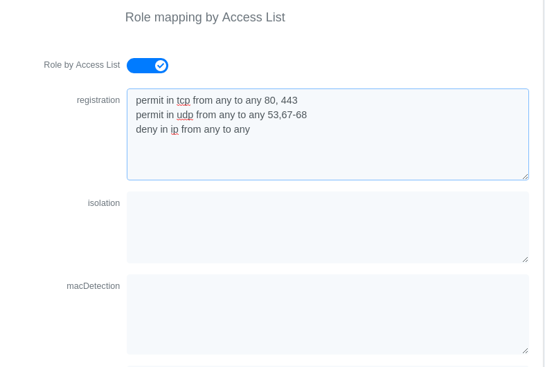
Now, your normal users are placed in the 'default' role and your guests in the 'guest' role.
The 'default' role uses the network 192.168.5.0/24 and 'guest' uses the network 192.168.10.0/24.
You can prevent communications between both networks using these access lists
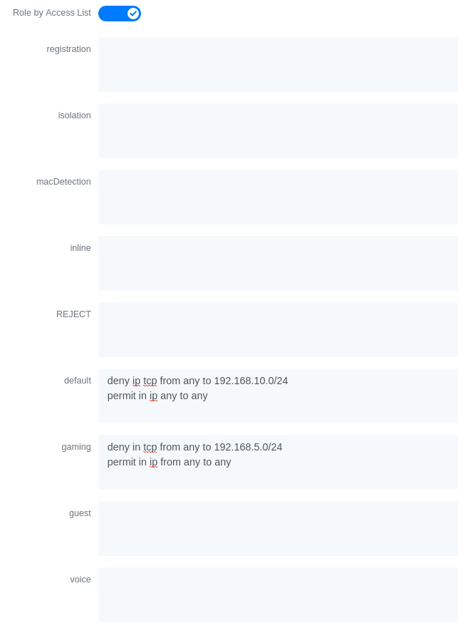
You could also only prevent your guest users from using shared directories
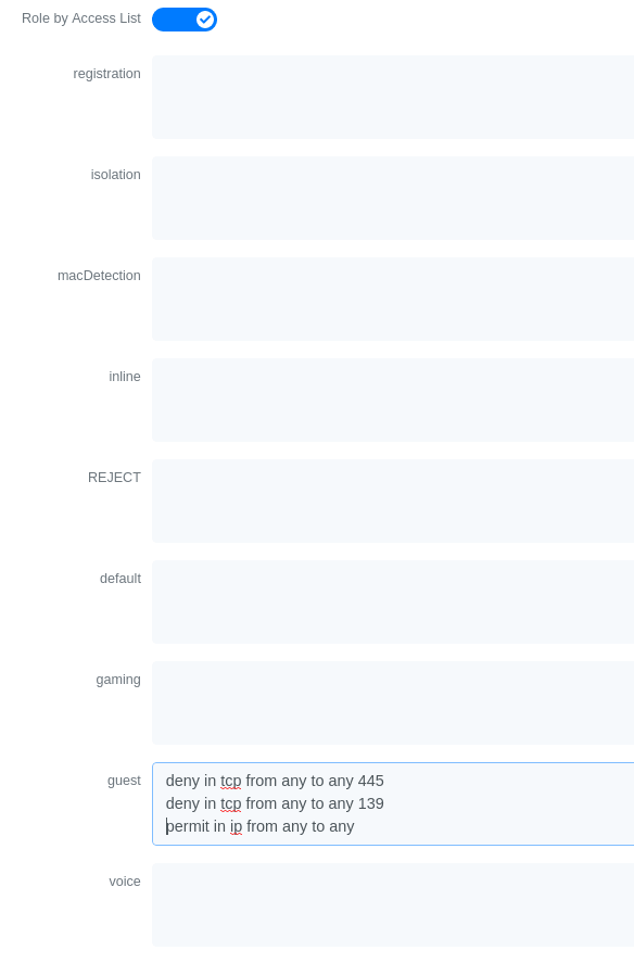
You could also restrict your users to use only your DNS server where 192.168.5.2 is your DNS server
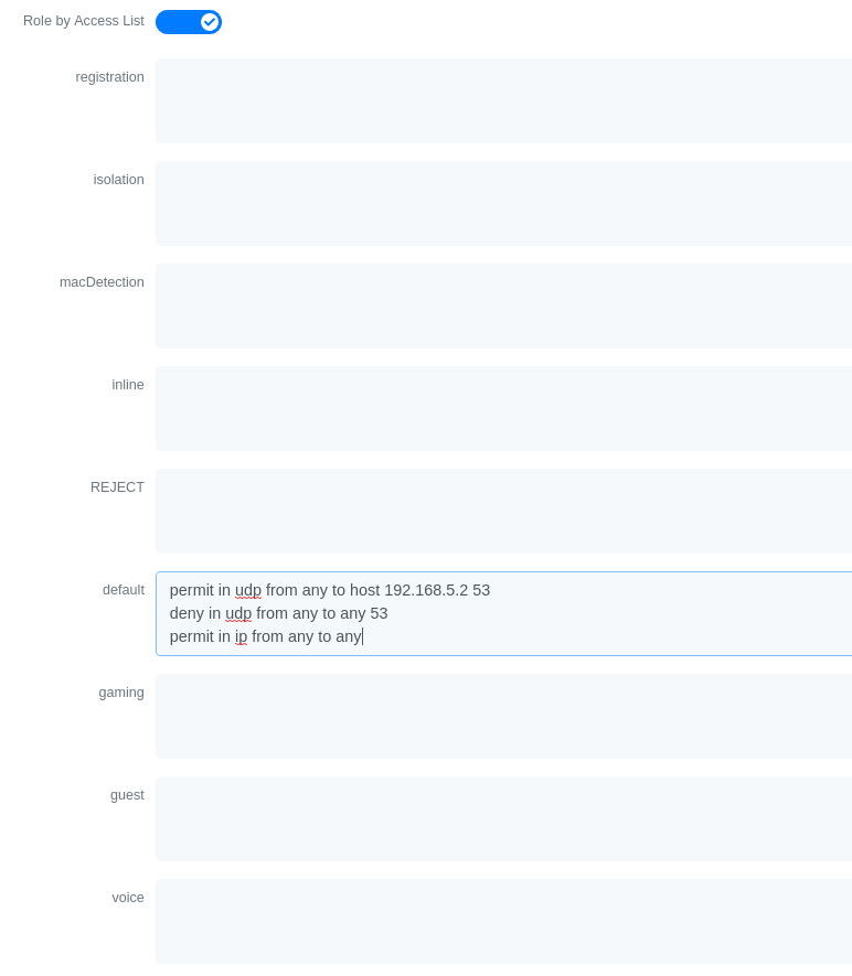
3.22. Huawei
PacketFence supports the S5710/S5720/S5735 switch from Huawei.
3.22.1. Global configuration
Global configuration for 802.1X, Mac authentication, accounting and CLI login:
undo authentication unified-moderadius-server template packetfenceradius-server shared-key cipher <yourSecret>radius-server authentication 192.168.1.5 1812radius-server accounting 192.168.1.5 1813radius-server retransmit 2# used for RADIUS Disconnect messagesradius-server authorization 192.168.1.5 shared-key cipher <yourSecret># to accept RADIUS Disconnect messages with MAC in AA-BB-CC-DD-FF-EE formatradius-server authorization calling-station-id decode-mac-format asciihyphen-split commonaaaauthentication-scheme pf-authauthentication-mode radiusaccounting-scheme pf-acctaccounting-mode radius# for CLI authenticationservice-scheme pf-clidomain pfauthentication-scheme pf-authaccounting-scheme pf-acctservice-scheme pf-cliradius-server packetfence# set default common domain used for authenticationdomain pf# if you want CLI login# domain pf admindot1x enablemac-authendot1x timer reauthenticate-period 10800mac-authen timer reauthenticate-period 10800dot1x dhcp-triggersnmp-agentsnmp-agent local-engineid 800007DB0304F9389D2360snmp-agent community read cipher <privateKey>snmp-agent community write cipher <privateKey>snmp-agent sys-info version v2c v3
3.22.2. SNMPv3
snmp-agent group v3 MYGROUP privacy read-view SNMP write-view SNMPsnmp-agent usm-user v3 MYUSERsnmp-agent usm-user v3 MYUSER group MYGROUPsnmp-agent usm-user v3 MYUSER authentication-mode md5 cipher SECRET1snmp-agent usm-user v3 MYUSER privacy-mode aes128 cipher SECRET2
3.22.3. MAC authentication
interface GigabitEthernet0/0/8dot1x mac-bypass mac-auth-firstdot1x mac-bypassdot1x max-user 1dot1x reauthenticatedot1x authentication-method eap
3.22.4. 802.1X with MAC Auth bypass
interface GigabitEthernet0/0/8port link-type hybriddot1x mac-bypassdot1x max-user 1dot1x reauthenticatedot1x authentication-method eap
3.22.5. Voice port
Configuration of a switchport where a phone is plugged:
interface GigabitEthernet0/0/2port link-type hybridvoice-vlan 100 enableport hybrid tagged vlan 100mac-authen
3.22.6. Troubleshooting commands
display aaa configurationdisplay dot1xdisplay access-userdisplay radius-servertest-aaa user password radius-template packetfence pap
3.23. IBM
3.23.1. RackSwitch G8052
PacketFence supports only 802.1X authentication. It has been tested on version 7.9.11.0.
RADIUS configuration
RS G8052(config)# radius-server primary-host 192.168.1.5RS G8052(config)# radius-server enableRS G8052(config)# radius-server primary-host 192.168.1.5 key useStrongerSecret
802.1X (dot1x) configuration
RS G8052(config)# dot1x enable
SNMP configuration
RS G8052(config)# snmp-server read-community packetfenceRS G8052(config)# snmp-server write-community packetfence
Port configuration
RS G8052(config)# configure terminalRS G8052(config)# interface port 1RS G8052(config-if)# dot1x mode autoRS G8052(config-if)# dot1x quiet-time 2RS G8052(config-if)# dot1x server-timeout 3RS G8052(config-if)# dot1x re-authenticateRS G8052(config-if)# dot1x re-authentication-interval 10800RS G8052(config-if)# dot1x vlan-assignRS G8052(config-if)# end
PacketFence configuration
To configure the IBM RackSwitch G8052 switch module, in the admin interface go to Configuration → Network Devices → Switches → Add switch
Definition:
IP: This will be the IP of the IBM StackSwitch G8052 switch on the managementnetworkDescription: IBM StackSwitch G8052Type: IBM RackSwitch G8052Mode: ProductionDeauthentication: SNMPDynamic Uplinks: Checked
Roles:
Role by VLAN ID: checkedregistration VLAN: 2isolation VLAN: 3default: 10
Radius:
Secret Passphrase: useStrongerSecret
Snmp:
SNMP Version: 2cSNMP Read Community: packetfenceSNMP Write Community: packetfence
Click Save to add the switch
3.24. Intel
3.24.1. Express 460 and Express 530
PacketFence support these switches without VoIP using one trap type:
- linkUp/linkDown
Exact command-line configuration to be contributed…
3.25. Intelbras
3.25.1. SC 5530
General Radius:
radius scheme packetfenceprimary authentication 192.168.1.5 key simple useStrongerSecretprimary accounting 192.168.1.5 key simple useStrongerSecretuser-name-format without-domainnas-ip interface Vlan-interface1
eap-profile packetfencemethod peap-mschapv2
domain packetfenceauthentication lan-access radius-scheme packetfenceauthorization lan-access radius-scheme packetfenceaccounting lan-access radius-scheme packetfenceauthentication default radius-scheme packetfence # RADIUS Cli login (optional)
domain default enable packetfence
dot1xdot1x authentication-method eapdot1x quiet-perioddot1x retry 3dot1x timer quiet-period 30dot1x timer handshake-period 30dot1x access-user log enable abnormal-logoff failed-login normal-logoff successful-login
mac-authentication
Radius COA:
radius dynamic-author serverclient ip 192.168.1.5 key simple useStrongerSecret
Dot1x:
interface Twenty-FiveGigE1/0/28port link-mode bridgemirroring-group 1 monitor-portdot1xdot1x re-authenticate
Mac authentication:
interface Twenty-FiveGigE1/0/34port link-mode bridgeport link-type trunkport trunk permit vlan 1mac-authentication
3.26. Juniper
PacketFence supports Juniper switches in MAC Authentication (Juniper’s MAC RADIUS) mode and 802.1X. PacketFence supports VoIP on the EX2200 (JUNOS 12.6) and EX4200 (JUNOS 13.2)
3.26.1. Junos Modules
Standard switch module supporting legacy Juniper switches using Junos versions before v12.x.
Junos v12.x and Junos v13.x
Junos v12.x and v13.x modules designed for switches operating on JuniperOS v12.x and v13.x. Inherits all functionalities from "EX2200 and EX4200" modules; all configurations below apply to Junos v12.x and v13.x.
Junos v15.x and Junos v18.x
Junos v15.x and v18.x modules designed for switches using JuniperOS v15.x and v18.x. Inherits all functionalities from "EX2200_v15 and EX2300" modules.
# load replace terminal[Type ^D at a new line to end input]interfaces {interface-range access-ports {member-range ge-0/0/1 to ge-0/0/46;unit 0 {family ethernet-switching {port-mode access;}}}}protocols {dot1x {authenticator {authentication-profile-name packetfence;interface {access-ports {supplicant multiple;mac-radius;}}}}}access {radius-server {192.168.1.5 {port 1812;secret "useStrongerSecret";}}profile packetfence {authentication-order radius;radius {authentication-server 192.168.1.5;accounting-server 192.168.1.5;}accounting {order radius;accounting-stop-on-failure;accounting-stop-on-access-deny;}}}ethernet-switching-options {secure-access-port {interface access-ports {mac-limit 1 action drop;}}}snmp {name "EX 4200";description juniper;location EX;contact "email@example.com";client-list list0 {192.168.1.5/32;}community public {authorization read-only;client-list-name list0;}community private {authorization read-write;client-list-name list0;}}Ctrl-D# commit comment "packetfenced"
Change the interface-range statement to reflect the ports you want to secure
with PacketFence.
3.26.2. VoIP configuration
# load replace terminal[Type ^D at a new line to end input]protocols{lldp {advertisement-interval 5;transmit-delay 1;ptopo-configuration-trap-interval 1;lldp-configuration-notification-interval 1;interface all;}lldp-med {interface all;}}ethernet-switching-options {secure-access-port {interface access-ports {mac-limit 2 action drop;}}voip {interface access-ports {vlan voice;forwarding-class voice;}}}}vlans {voice {vlan-id 3;}}Ctrl-D# commit comment "packetfenced VoIP"
3.26.3. 802.1X configuration
protocols {dot1x {authenticator {authentication-profile-name packetfence;interface {access-ports {supplicant multiple;mac-radius;}}}}}Ctrl-D# commit comment "packetfenced dot1x"
3.26.4. MAC Authentication configuration
protocols {dot1x {authenticator {authentication-profile-name packetfence;interface {access-ports {supplicant multiple;mac-radius {restrict;}}}}}}Ctrl-D# commit comment "packetfenced mac auth"
3.26.5. Configuration for MAC authentication floating devices
To support floating devices on a Juniper switch you need to configure the 'flap-on-disconnect' option on each interface individually and remove it from the access-ports group.
# load replace terminal[Type ^D at a new line to end input]protocols {dot1x {authenticator {authentication-profile-name packetfence;interface {ge-0/0/1.0 {mac-radius{flap-on-disconnect;}}ge-0/0/2.0 {mac-radius{flap-on-disconnect;}}.....access-ports {supplicant multiple;mac-radius {restrict;}}}}}}Ctrl-D# commit comment "configured for floating devices"
flap-on-disconnect option takes effect only
when the restrict option is also set.3.26.6. Radius CLI login
set system authentication-order [ radius password ]set system radius-server 192.168.1.5 secret useStrongerSecretset system login user RO class read-onlyset system login user SU class super-user
3.27. LG-Ericsson
PacketFence supports iPECS series switches without VoIP using two different trap types:
- linkUp / linkDown
- Port Security (with static MACs)
On some recent models, we can also use more secure and robust features, like:
- MAC Authentication
- 802.1X
3.27.1. ES-4500G Series
LinkUp / LinkDown
Firmware 1.2.3.2 is required for linkUp / linkDown
Prior to config, make sure to create all necessaries VLANs and config the appropriate uplink port.
Global config settings
snmp-server community public rosnmp-server community private rw!snmp-server enable traps authenticationsnmp-server host 192.168.1.5 public version 2c udp-port 162snmp-server notify-filter traphost.192.168.1.5.public remote 192.168.1.5
Firmware is kinda buggy so you’ll need to enable linkUp / linkDown using the Web Interface under Administration → SNMP.
Some reports shows that the switch doesn’t always send linkDown traps.
On each interface (except uplink)
switchport allowed vlan add 4 untaggedswitchport native vlan 4switchport allowed vlan remove 1switchport mode access
Port-Security
Firmware 1.2.3.2 is required for port-security.
Prior to config, make sure to create all necessaries VLANs and config the appropriate uplink port.
Global config settings
snmp-server community public rosnmp-server community private rw!snmp-server enable traps authenticationsnmp-server host 192.168.1.5 public version 2c udp-port 162snmp-server notify-filter traphost.192.168.1.5.public remote 192.168.1.5
On each interface (except uplink)
port security max-mac-count 1port securityport security action trapswitchport allowed vlan add 2 untaggedswitchport native vlan 2switchport allowed vlan remove 1switchport mode access
The above port security command may not work using the CLI. In this case, use the Web Interface under the Security → Port Security menu and enable each ports using the checkboxes.
It is also recommended, when using port-security, to disable link-change (UP / DOWN) traps.
Don’t forget to update the startup config!
3.28. Linksys
PacketFence supports Linksys switches without VoIP using one trap type:
- linkUp/linkDown
Don’t forget to update the startup config!
3.28.1. SRW224G4
Global config settings
no snmp-server trap authenticationsnmp-server community CS_2000_le rw view Defaultsnmp-server community CS_2000_ls ro view Defaultsnmp-server host 192.168.1.5 public 2
On each interface
switchport access vlan 4
3.29. Netgear
The "web-managed smart switch" models GS108Tv2/GS110/GS110TP are supported with Link up/down traps only.
Higher-end "fully managed" switches including FSM726v1 are supported in Port Security mode.
3.29.1. FSM726 / FSM726S version 1
PacketFence supports FSM726 / FSM726S version 1 switches without VoIP in Port Security mode (with static MACs) – called Trusted MAC table on Netgear’s hardware.
Using the HTTP GUI, follow the steps below to configure such feature. Of course, you must create all your VLANs on the switch as well.
SNMP Settings
In Advanced → SNMP → Community Table, create a read-write community string and a trap community string. You can use the same community for all the 3 functions (Get, Set, Trap).
Next, under Advanced → SNMP → Host Table, enable the Host Authorization feature and add the PacketFence server into the allowed host list.
Finally, under Advanced → SNMP → Trap Setting, enable the authentication trap.
Trusted MAC Security
Under Advanced → Advanced Security → Trusted MAC Address, create a fake MAC
address per port (ie. 02:00:00:00:00:xx where xx is the port number). This
will have the effect of sending a security trap to PacketFence when a new device
plugs on the port.
Don’t forget to save the configuration!
3.29.2. GS108Tv2 / GS110T / GS110TP
PacketFence supports certain lower-end Netgear switches in Link Up/Link Down traps. These "web-managed" switches have no command-line interface and only a subset of the port security and 802.1X functionality needed to interoperate with PacketFence in these more advanced modes. There is no way to send a trap upon port security violation, and there is only pure 802.1X, no MAC Address Bypass.
Switch Configuration
It can be difficult to find the advanced features in the web GUI. We recommend using the GUI "Maintenance" tab to Upload the configuration to a file, and then edit it there.
Hints on file upload/download:
From the File Type menu, choose Text Configuration.
If you’re uploading to the TFTP root directory, leave Path blank.
At the top of the config file, you need:
vlan databasevlan 1,2,3,4,5vlan name 1 "Normal"vlan name 2 "Registration"vlan name 3 "Isolation"vlan name 4 "MAC Detection"vlan name 5 "Guest"exit
In the same section as "users passwd", you need to specify your PacketFence server’s management address:
snmptrap useStrongerSecret ipaddr 192.168.1.5
In the same section as the "voip oui" lines, you need to allow your SNMP server:
snmp-server community "public"snmp-server community rw useStrongerSecretsnmp-server community ipaddr 192.168.1.5 publicsnmp-server community ipmask 255.255.255.0 publicsnmp-server community ipaddr 192.168.1.5 useStrongerSecretsnmp-server community ipmask 255.255.255.0 useStrongerSecretno voip vlan
You should use port 1 as the uplink. If you connect port 1 of a GS108Tv2 switch into a Power over Ethernet switch, then the GS108Tv2 does not need AC power. If you bought GS110T(P) switches, presumably it’s for the SFP uplink option. You’ll want to configure both port 1 and the SFP ports 9-10 as trunks:
interface 0/1no snmp trap link-statusip dhcp filtering trustvlan pvid 1vlan ingressfiltervlan participation include 1,2,3,4,5vlan tagging 2,3,4,5no auto-voipexit
Each user-facing, PacketFence-managed port should be configured like:
interface 0/2vlan pvid 4vlan ingressfiltervlan participation include 4no auto-voipexit
3.29.3. M Series
PacketFence supports the Netgear M series in wired MAC authentication without VoIP.
Switch configuration
radius server host auth 192.168.1.5 radius server key auth 192.168.1.5 (then press enter and input your secret) radius server primary 192.168.1.5 radius server host acct 192.168.1.5 radius server key acct 192.168.1.5 (then press enter and input your secret)
aaa session-id unique dot1x system-auth-control aaa authentication dot1x default radius authorization network radius radius accounting mode
On your interfaces
interface 0/x dot1x port-control mac-based dot1x timeout guest-vlan-period 1 dot1x mac-auth-bypass exit
3.30. Nortel
PacketFence supports Nortel switches with VoIP using one trap type:
- Mac Security
Don’t forget to update the startup config!
/usr/local/pf/conf/switches.conf. Indeed, Nortel introduced an incompatible
change of behavior in this firmware.3.30.1. BayStack 470, ERS2500 Series, ERS4500 Series, 4550, 5500 Series and ES325
Global config settings
snmp-server authentication-trap disablesnmp-server host 192.168.1.5 "public"snmp trap link-status port 1-24 disableno mac-security mac-address-tableinterface FastEthernet ALLmac-security port ALL disablemac-security port 1-24 enabledefault mac-security auto-learning port ALL max-addrsexitmac-security enablemac-security snmp-lock disablemac-security intrusion-detect disablemac-security filtering enablemac-security snmp-trap enablemac-security auto-learning aging-time 60mac-security learning-ports NONEmac-security learning disable
VoIP support
You need to ensure that all your ports are tagged with the voice VLAN. The switch should do the rest for you.
vlan create 6 name "Telephone" type port learning ivlvlan members 6 1-20,23-24
3.30.2. BPS2000
You can only configure this switch through menus.
Enable MAC Address Security:
MAC Address Security: EnabledMAC Address Security SNMP-Locked: DisabledPartition Port on Intrusion Detected: DisabledDA Filtering on Intrusion Detected: EnabledGenerate SNMP Trap on Intrusion: EnabledCurrent Learning Mode: DisabledLearn by Ports: NONEPort Trunk Security---- ----- --------1 Enabled...24 Enabled
3.31. Pica8
PacketFence supports Pica8 switches without VoIP using CoA to:
- bounce-host-port
- reauthenticate-host
Notes
- SNMP is not supported yet
- Port Security is not supported
For interfaces with MAC Authentication, perform the following:
set interface gigabit-ethernet ge-1/1/25 family ethernet-switching port-modetrunkset protocols dot1x interface ge-1/1/25 auth-mode mac-radiusset protocols dot1x interface ge-1/1/25 dynamic-vlan-enable trueset protocols dot1x traceoptions interface ge-1/1/25 flag all disable false
For interfaces with 802.1X, perform:
set interface gigabit-ethernet ge-1/1/4 family ethernet-switching port-modetrunkset protocols dot1x interface ge-1/1/4 auth-mode dot1xset protocols dot1x interface ge-1/1/4 dynamic-vlan-enable trueset protocols dot1x traceoptions interface ge-1/1/4 flag all disable false
Global configuration:
set protocols dot1x aaa radius nas-ip 10.10.51.169set protocols dot1x aaa radius authentication server-ip 192.168.1.5 shared-keyuseStrongerSecretset protocols dot1x aaa radius dynamic-author client 192.168.1.5 shared-keyuseStrongerSecretset protocols dot1x traceoptions interface ge-1/1/4 flag all disable falseset protocols dot1x traceoptions flag radius disable falseset vlans vlan-id 10set vlans vlan-id 20set vlans vlan-id 30commit
-
10.10.51.169is the switch IP - For interfaces where auth-mode is unknown, use the following command set protocols dot1x interface ge-1/1/12 auth-mode dot1x-mac-radius This allows the switch to first try 802.1X and if there is no response from the client then fallback to MAC Authentication.
- Create VLAN(s) on the switch as per your requirements
- Please note that traceoptions are only for debugging
3.32. SMC
3.32.1. TigerStack 6128L2, 8824M and 8848M
PacketFence supports these switches without VoIP using two different trap types:
- linkUp/linkDown
- Port Security (with static MACs)
We recommend to enable Port Security only.
Global config settings
SNMP-server host 192.168.1.5 public version 2c udp-port 162no snmp-server enable traps link-up-down
On each interface:
port security max-mac-count 1port securityport security action trap
3.32.2. TigerStack 6224M
Supports linkUp/linkDown mode
Global config settings
SNMP-server host 192.168.1.5 public version 1
3.33. Ubiquiti
3.33.1. EdgeSwitch
PacketFence supports the EdgeSwitch with the following techniques:
- 802.1X with MAC Authentication fallback
- 802.1X with MAC Authentication fallback with VoIP
802.1X with MAC Authentication fallback
Switch IP assumed: 192.168.1.254
Uplink configuration:
dot1x port-control force-authorizedvlan participation include 1,2,3,4,5,100vlan tagging 2,3,4,5,100
Global config settings:
vlan databasevlan 1vlan 2vlan 3vlan 4vlan 5vlan 100exit
configuredot1x system-auth-controlaaa authentication dot1x default radiusauthorization network radiusdot1x dynamic-vlan enableradius accounting moderadius server host auth "192.168.1.5" name "PacketFence"radius server key auth "192.168.1.5"
Enter secret (64 characters max):useStrongerSecret
radius server primary "192.168.1.5"no radius server msgauth "192.168.1.5"radius server attribute 4 192.168.1.254
radius server attribute 32 "EdgeSwitch"radius server host acct "192.168.1.5" name PacketFence-ACCTradius server key acct "192.168.1.5"
Enter secret (64 characters max):useStrongerSecret
snmp-server community public rosnmp-server community private rwexit
On each interface (not uplink)
dot1x port-control mac-baseddot1x re-authenticationdot1x timeout reauth-period 1800dot1x timeout supp-timeout 10dot1x timeout guest-vlan-period 3dot1x timeout server-timeout 1800dot1x mac-auth-bypassdot1x unauthenticated-vlan 4vlan participation include 1,2,3,4,5,100exit
802.1X with MAC Authentication fallback with VoIP
Switch IP assumed: 192.168.1.254
Uplink configuration:
dot1x port-control force-authorizedvlan participation include 1,2,3,4,5,100vlan tagging 2,3,4,5,100
Global config settings:
vlan databasevlan 1vlan 2vlan 3vlan 4vlan 5vlan 100exit
configuredot1x system-auth-controlaaa authentication dot1x default radiusauthorization network radiusdot1x dynamic-vlan enablevoice vlan 100radius accounting moderadius server host auth "192.168.1.5" name "PacketFence"radius server key auth "192.168.1.5"
Enter secret (64 characters max):useStrongerSecret
radius server primary "192.168.1.5"no radius server msgauth "192.168.1.5"radius server attribute 4 192.168.1.254
radius server attribute 32 "EdgeSwitch"radius server host acct "192.168.1.5" name PacketFence-ACCTradius server key acct "192.168.1.5"
Enter secret (64 characters max):useStrongerSecret
snmp-server community public rosnmp-server community private rwexit
On each interface (not uplink)
dot1x port-control mac-baseddot1x re-authenticationdot1x timeout reauth-period 1800dot1x timeout supp-timeout 10dot1x timeout guest-vlan-period 3dot1x timeout server-timeout 1800dot1x mac-auth-bypassdot1x unauthenticated-vlan 4vlan participation include 1,2,3,4,5,100voice vlan 100auto-voip protocol-basedlldp transmitlldp receivelldp transmit-tlv port-desclldp transmit-tlv sys-namelldp transmit-tlv sys-desclldp transmit-tlv sys-caplldp transmit-mgmtlldp notificationlldp medlldp med confignotificationexit
4. Wireless Controllers and Access Point Configuration
4.1. Assumptions
Network infrastructure assumptions for this configuration:
- PacketFence fully configured with FreeRADIUS running
- PacketFence IP address: 192.168.1.5
- Normal VLAN: 1
- Registration VLAN: 2
- Isolation VLAN: 3
- MAC Detection VLAN: 4
- Guest VLAN: 5
- VoIP, Voice VLAN: 100
- use SNMP v2c
- SNMP community name: public
- RADIUS Secret: useStrongerSecret [1]
- Open SSID: PacketFence-Public
- WPA-Enterprise SSID: PacketFence-Secure
4.2. Unsupported Equipment
Wireless network access configuration is more consistent between vendors due to standardization compared to wired side: VLAN assignment done centrally with RADIUS and consistent client protocol (MAC-Authentication or 802.1X).
This consistency means most wireless network devices work out-of-the-box with PacketFence. Only missing piece typically: remote client deauthentication for VLAN assignment (deauth user to reconnect and get new VLAN).
Even if your wireless equipment isn’t explicitly supported by PacketFence, try it. Next section covers objectives for testing equipment without existing configuration.
Here are the high-level requirements for proper wireless integration with PacketFence
- The appropriate VLANs must exist
- Allow controller to honor VLAN assignments from AAA (sometimes called AAA override)
- Put your open SSID (if any) in MAC-Authentication mode and authenticate against the FreeRADIUS hosted on PacketFence
- Put your secure SSID (if any) in 802.1X mode and authenticate against FreeRADIUS hosted on PacketFence.
- On registration / isolation VLANs the DHCP traffic must reach the PacketFence server
-
On your production VLANs a copy of the DHCP traffic must reach PacketFence where a pfdhcplistener listens (configurable in
pf.confunderinterfaces)
At this point, user registration with the captive-portal is possible and registered users should have access to the appropriate VLANs. However, VLAN changes (like after a registration) won’t automatically happen, you will need to disconnect / reconnect. An explanation is provided in introduction section above about this behavior.
You can try modules similar to your equipment if any (read appropriate instructions) or you can try to see if RFC3576 is supported. RFC3576 covers RADIUS Packet of Disconnect (PoD) also known as Disconnect Messages (DM) or Change of Authorization (CoA). You can try the Aruba module if you want to verify if RFC3576 is supported by your hardware.
If none of the above worked then you can fallback to inline enforcement or let us know what equipment you are using on the packetfence-devel mailing list.
4.3. Aerohive Networks
Aerohive products are a bit different compared to the other vendors. They support either a local HiveManager (similar to a wireless controller) or a cloud-based HiveManager. However, the configuration is the same for the local and the cloud-based controller. Note that all the configurations are made on the HiveManager and then pushed to the APs.
4.3.1. MAC Authentication and 802.1X Configuration
Assumptions
- the network architecture is in order to give acces to the Aerohive Access Point, and has access to Internet
- the VLANs are defined for registration, isolation and management networks
-
from this documentation, we will assume that the VLANs tags are define like following:
- PacketFence Management VLAN: 1 IP address: 192.168.1.5
- registration VLAN ID 2, subnet 192.168.2.0/24
- isolation VLAN ID 3, subnet 192.168.3.0/24
- production VLAN ID 10, subnet 172.16.1.0/24
- the VLANs are spanned in the switches and switching L2 equipments, from the Production Network to the PacketFence server(s)
- the VLANs are allowed in the trunks
- Aerohive Access Point is loaded with HiveOS with version 6 or later
- HiveManager with version 6 or later
- Wireless AP: 172.16.1.1
- RADIUS Secret: useStrongerSecret
Configure the Aerohive APs and SSID
Logon to your HiveManager interface:
- for this example, we assume that we are on the Cloud MyHive.aerohive.com solution
- from HiveManager, click on your HiveManagerOnline Instances VHM-XXXXXX
- from Network Configuration / 1-Choose Network Policy, click on New
- give a name to your Policy, and click Create
- from 2-Configure Interfaces and User Access, SSID, click on Choose and click on New
- give a SSID Profile Name, SSID Name
For an open (no encryption) SSID using MAC-based authentication:
-
click on New
- SSID Access Security: Open
- check the box Enable MAC authentication
- click on Save
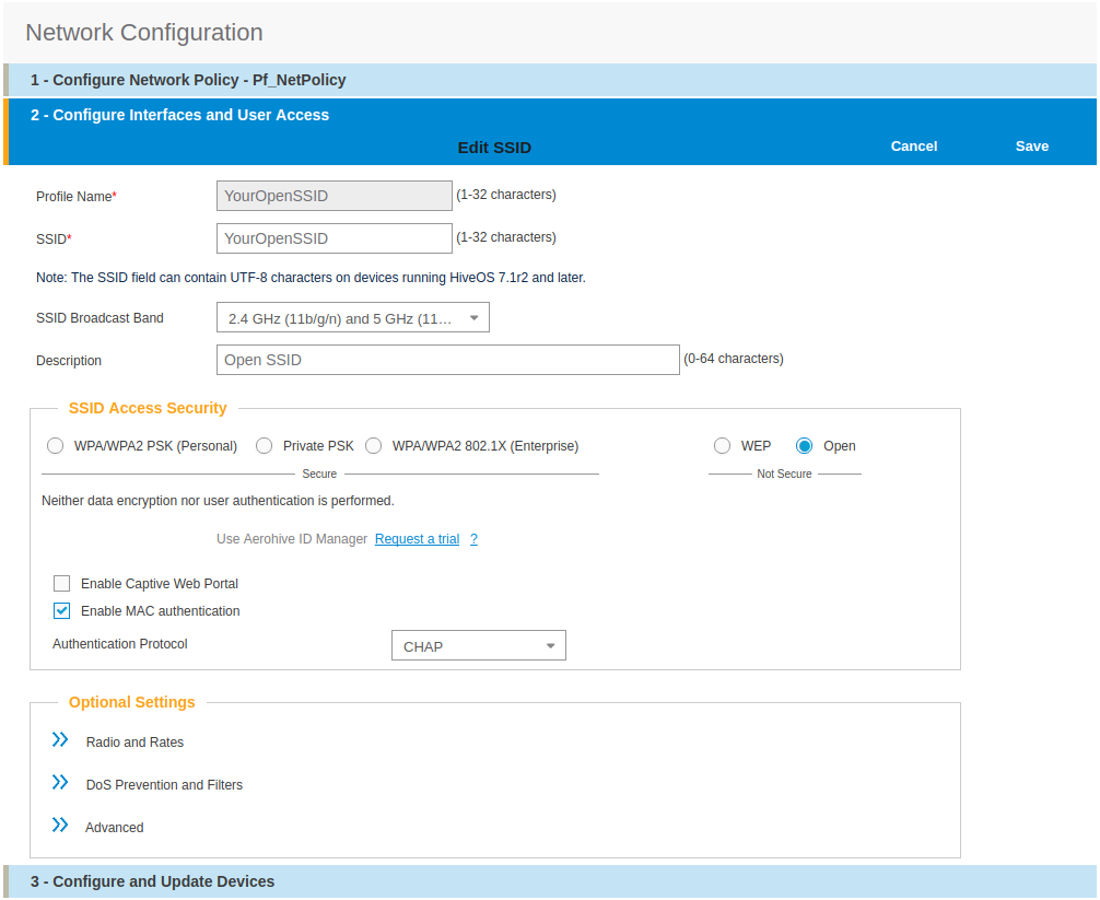
For a secure SSID using 802.1X:
-
click on New
- SSID Access Security: WPA/WPA2 802.1X (Enterprise)
- Key Management; WPA2-(WPA2 enterprise)-802.1X
- Encryption method: CCMP (AES)
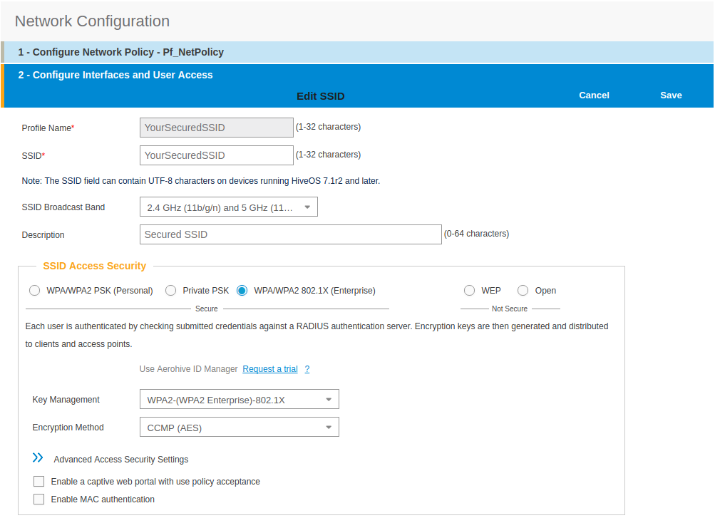
- click on Save
- from SSID, be sure to have selected both SSIDs previously created, and click OK
Add the RADIUS parameters created before:
- under Authentication click on <RADIUS Setting>, and click on New
- from RADIUS Name, give the name of the PaketFence server, for example
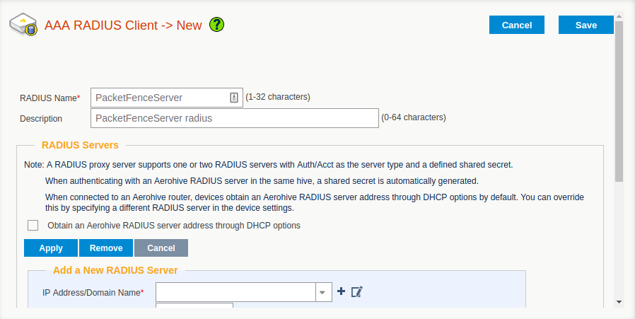
- from Add a New RADIUS Server, in IP Address/Domain Name, put the PacketFence Server IP
- hive the Shared Secret (useStrongerSecret) and Confirm it
- and Click on Apply
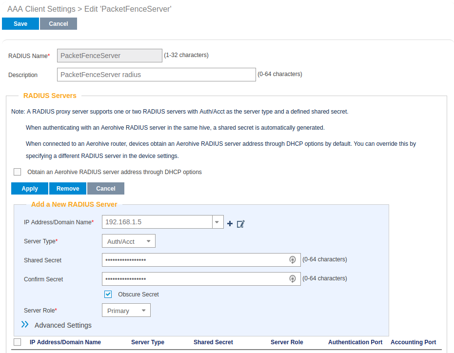
- deploy the Optionnal Setting(not supported by RADIUS Proxy) section and check the Permit Dynamic Change of Authorization Message (RFC 3576)
- click on Save
- next to your SSID Name Click on the <RADIUS Setting>, Click OK
We will create the default VLAN to be assign by the AP, when a new endpoint get in the SSID:
-
Under User Profile, Click on Add/Remove,and Click on New, in the Default section
- You will need to create one User Profile for each VLANs used, for us, we will create 3 Users Profiles, Registration, Isolation and Production
- from name, give the name of a rule to manage the VLANs with PacketFence (Registration ; Isolation ; Production)
- from Attribute Name, give the VLAN ID of the VLAN
- from Default VLan, Click on the (+) (New)
- as a VLAN ID, give the VLAN ID earlier Registration(2) , Isolation(3) or Production(10)
- click on Save and click on Save again on the Configure interfaces and User Access
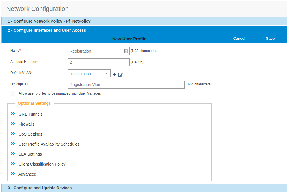
Create and add the other VLANs:
- Follow the same procedure to create the others VLANs
Once done with the VLANs configuration:
- From the Choose User Profiles, select the Default tab and click on you Registration VLAN tag
- From the Authentication tab, select the Isolation and the Production VLANs tag
- Click on Save
For our example, here is what it looks like, with two SSIDs
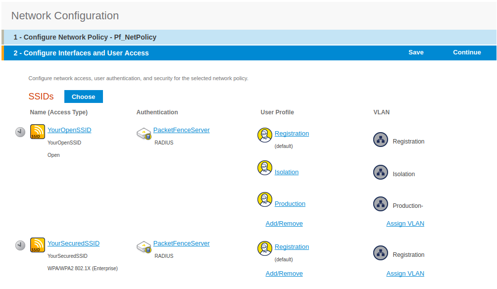
Then, click on Continue, on top right of the page.
Push your configuration to your AP:
- from Configure and Update Devices, check your AP in Device to Update
- click on Update
- select Update Devices
- from HiveOS Number of devices running earlier versions of HiveOS, select Upgrade these devices to the latest version of HiveOS
- click on Update
- wait until the date and time apprears under Update Status
Configure PacketFence
We will now need to create a new switch in PacketFence to be able to manage the endpoints behind the Aerohive APs.
Logon to your PacketFence interface:
- from Configuration / Policies and Access Control / Switches /
- on the line where there is the default, on the right, Click on CLONE
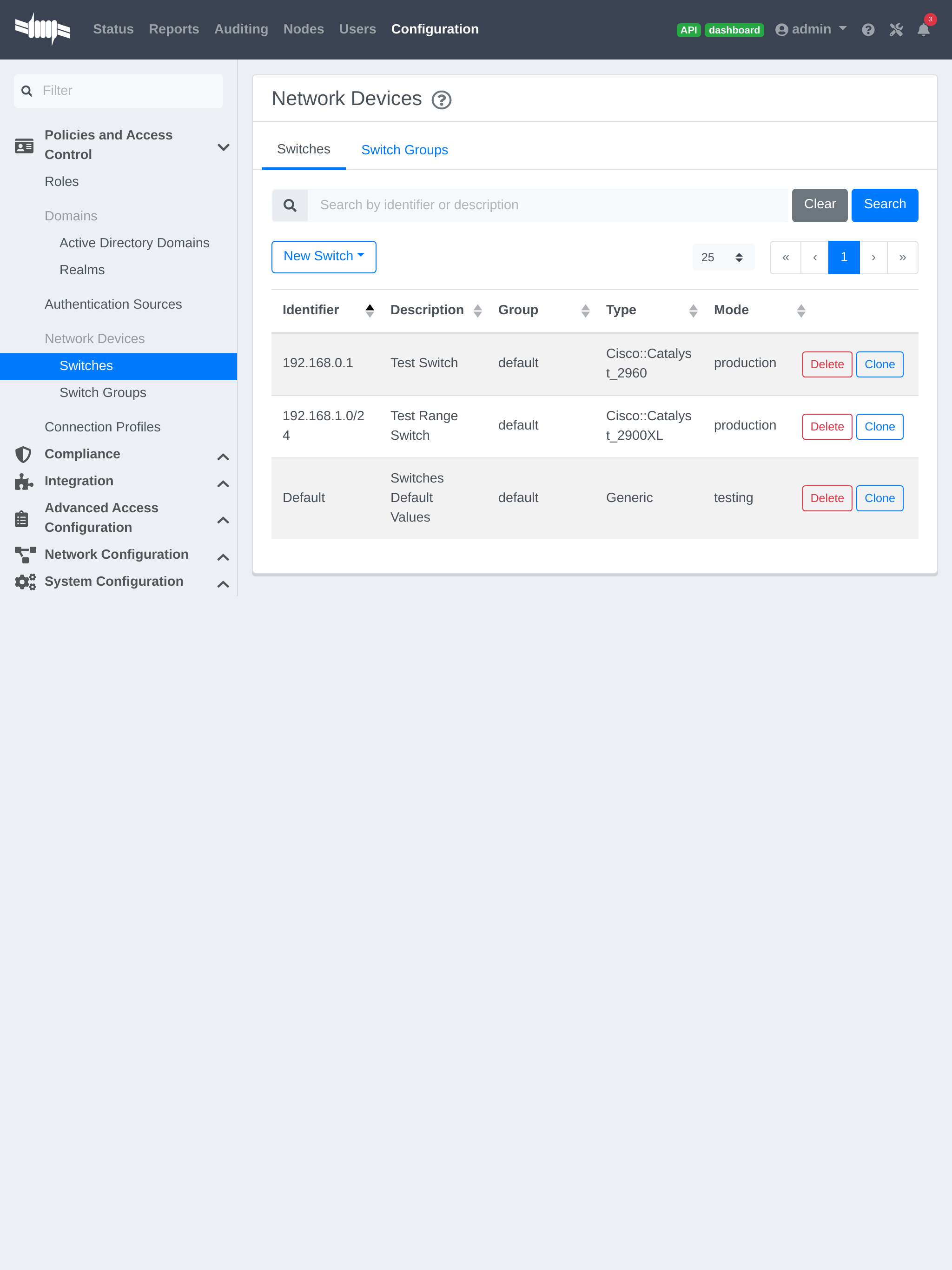
In Definition:
- IP Address/MAC Address/Range (CIDR), give the network address of your Production network; For us, it will be 172.16.1.1
- Description, give a description so you can quickly see what it is about
- from the Type list, select Aerohive AP
- from Mode select Production
- Switch Group by default set to None
- Deauthentication Method set to RADIUS
- click SAVE
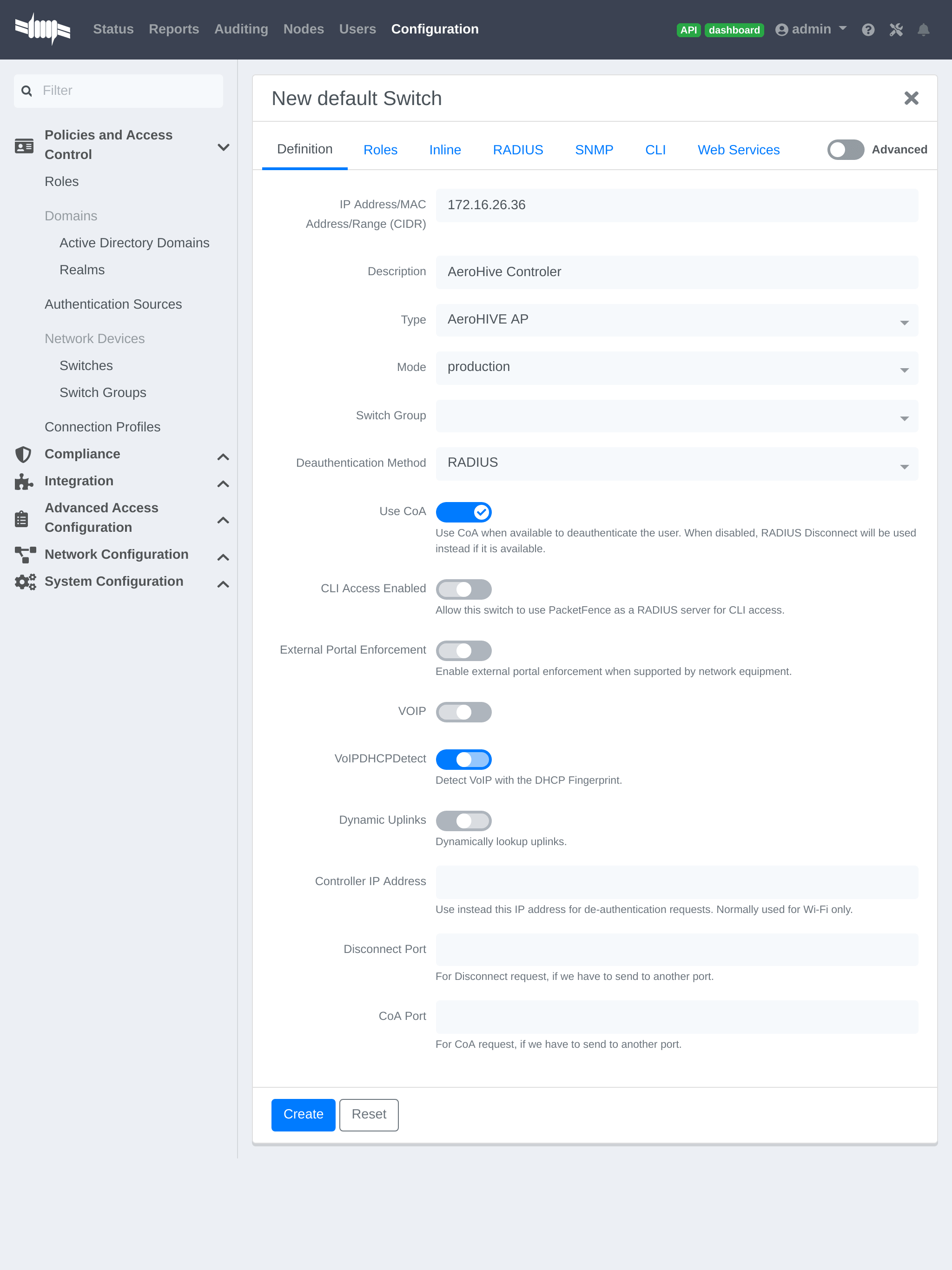
From Role:
- set all VLAN ID for each roles
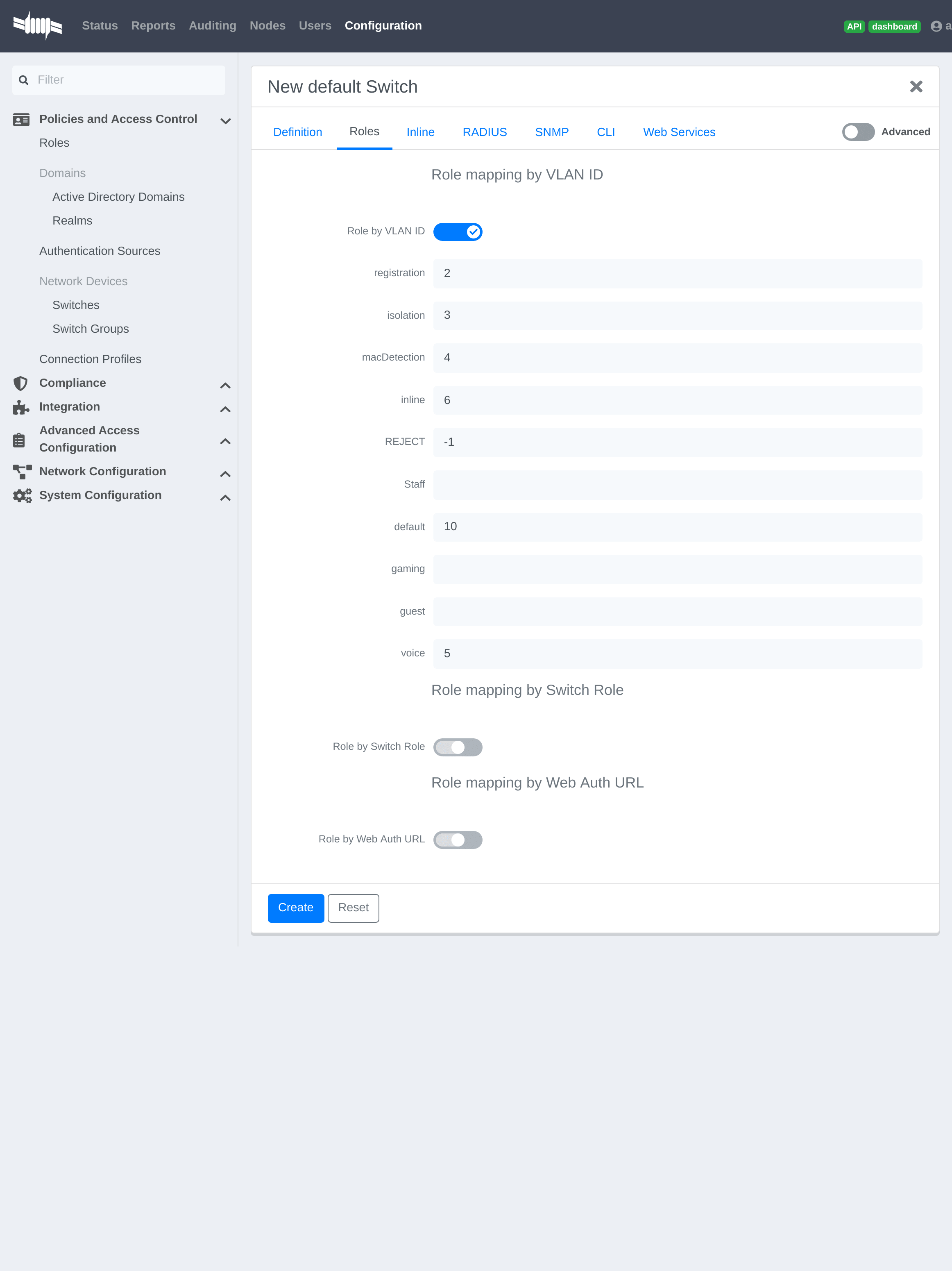
From RADIUS:
- modify the secret passphrase previously sets in the Aerohive HiveManager
- click on SAVE
This ends the PacketFence configuration.
4.3.2. Web Auth (External Captive Portal) Configuration
In this section we will describe the WebAuth configuration using PacketFence as an external captive poral.
Assumptions
In this part, it is recommended that the default VLAN must be the native VLAN. This way, the AP and the others network equipments will be able to manage VLANs.
You already have a Network Policy and at least one Access Point configured.
Configure the external captive portal
Create a new Captive Portal Profile:
- from the HiveManager, go to CONFIGURATION → ADVANCED CONFIGURATION → AUTHENTICATION → Captive Web Portals
- click on New
- give it a name
- Registration Type must be External Authentication
- click on Captive Web Portal Login Page Settings to deploy the configuration window
- Login URL must be http://192.168.1.5/AeroHIVE::AP
- Password Encryption : No Encryption (Plaintext Password)
- click on Save
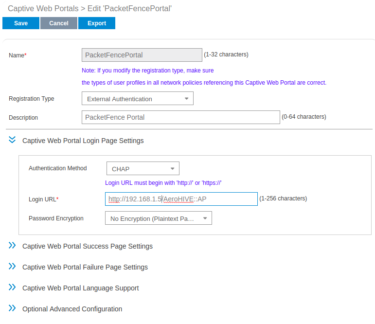
Create a SSID to enable Captive Portal functionality:
- from the HiveManager, go to CONFIGURATION → SSIDS
- click on the New button
- give your Profile and SSID a name
- from SSID Access Security , Check Enable Captive Web Portal
- before clicking on the button Save you should have something like this:
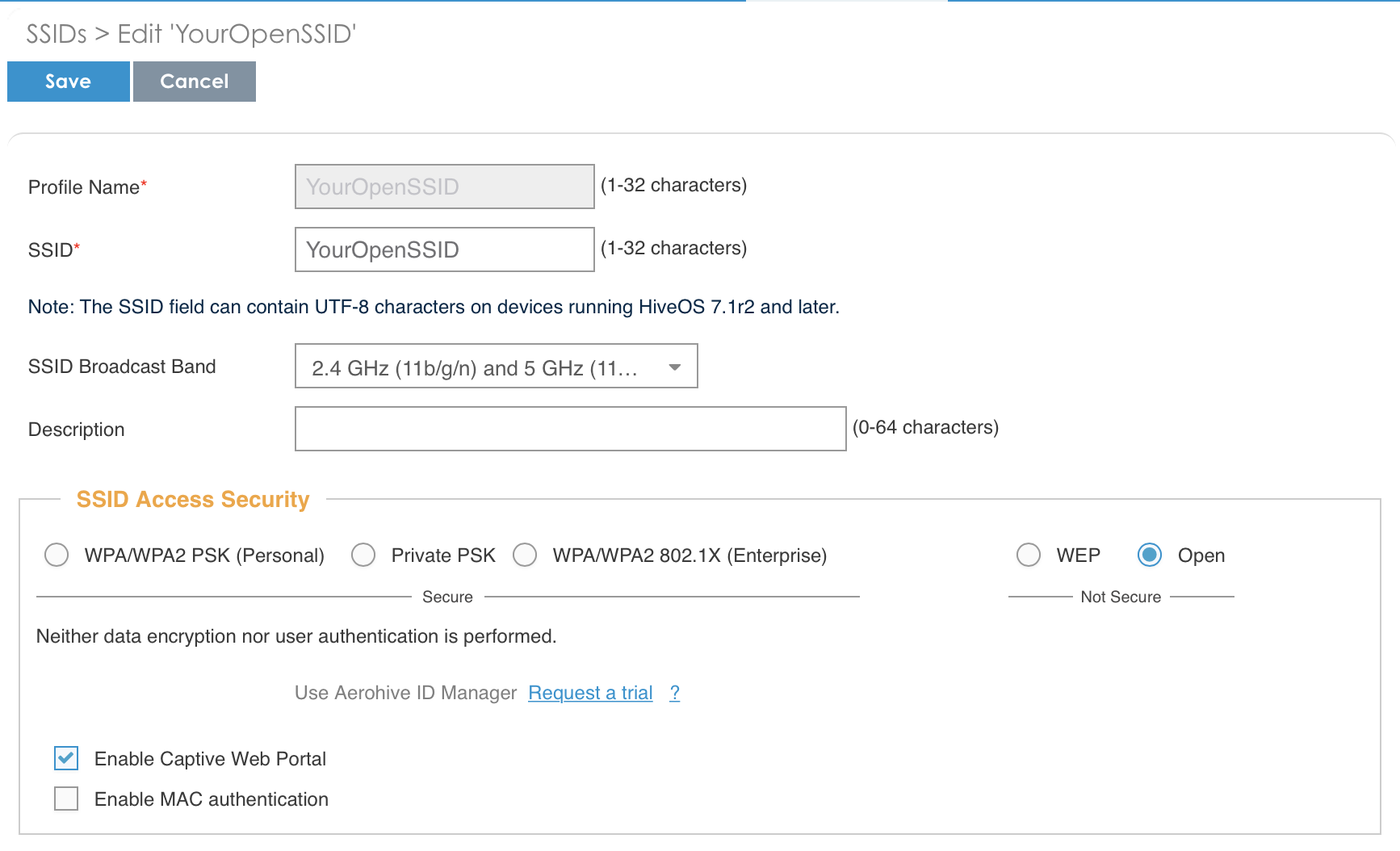
Configure and broadcast your SSID:
- from the HiveManager, go to CONFIGURATION → NETWORK POLICIES
- choose Network Policy and click OK, you should see this:
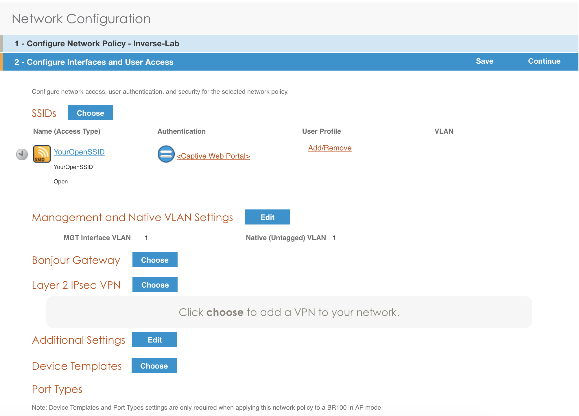
- under Authentication click on <Captive Web Portal> and select the captive portal previously configured
- once the <RADIUS Settings> appears under the captive portal, click on it
- on that new window Choose RADIUS click New
- give it a description and a name
- under RADIUS Servers click New
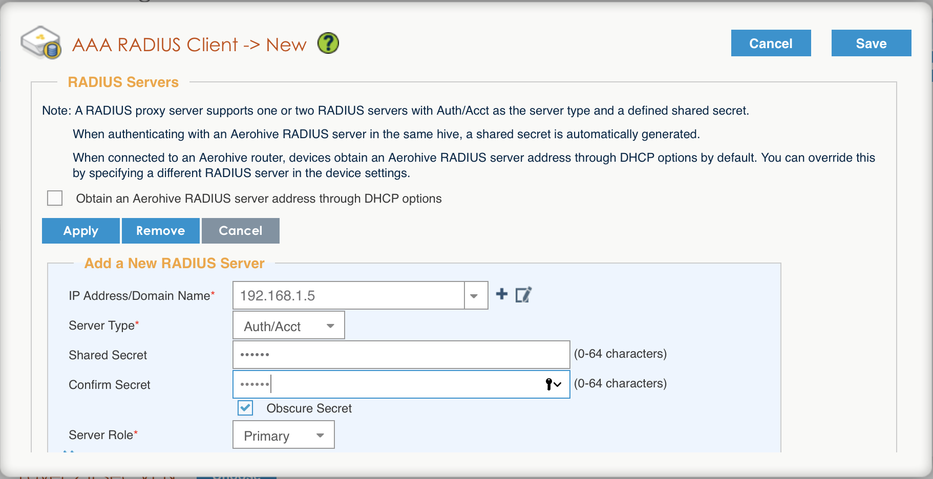
- click on Apply
- click on Optional Settings (not supported by RADIUS Proxy) and check Permit Dynamic Change of Authorization Messages (RFC 3576)
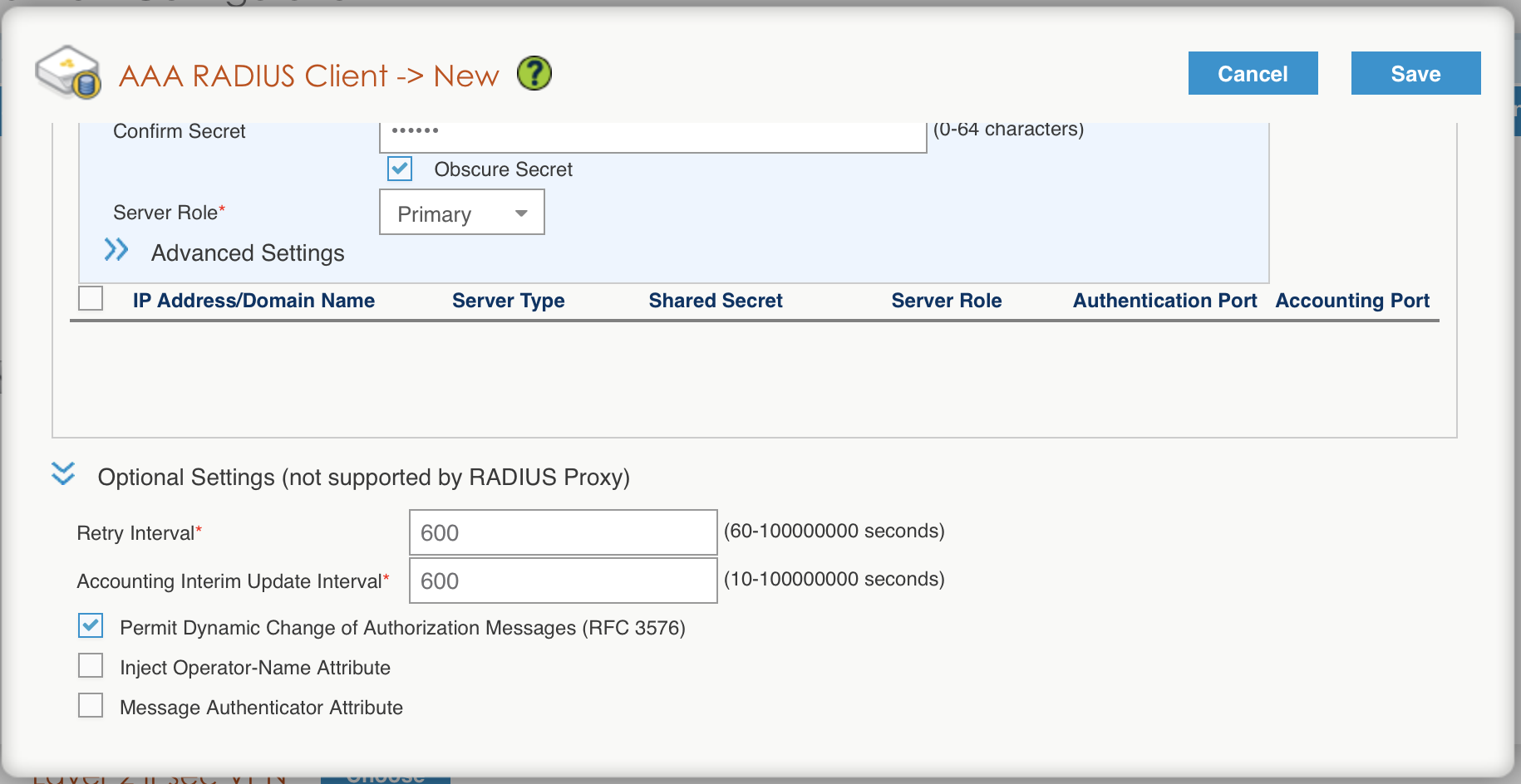
- click on the Save button
Configure the User profile:
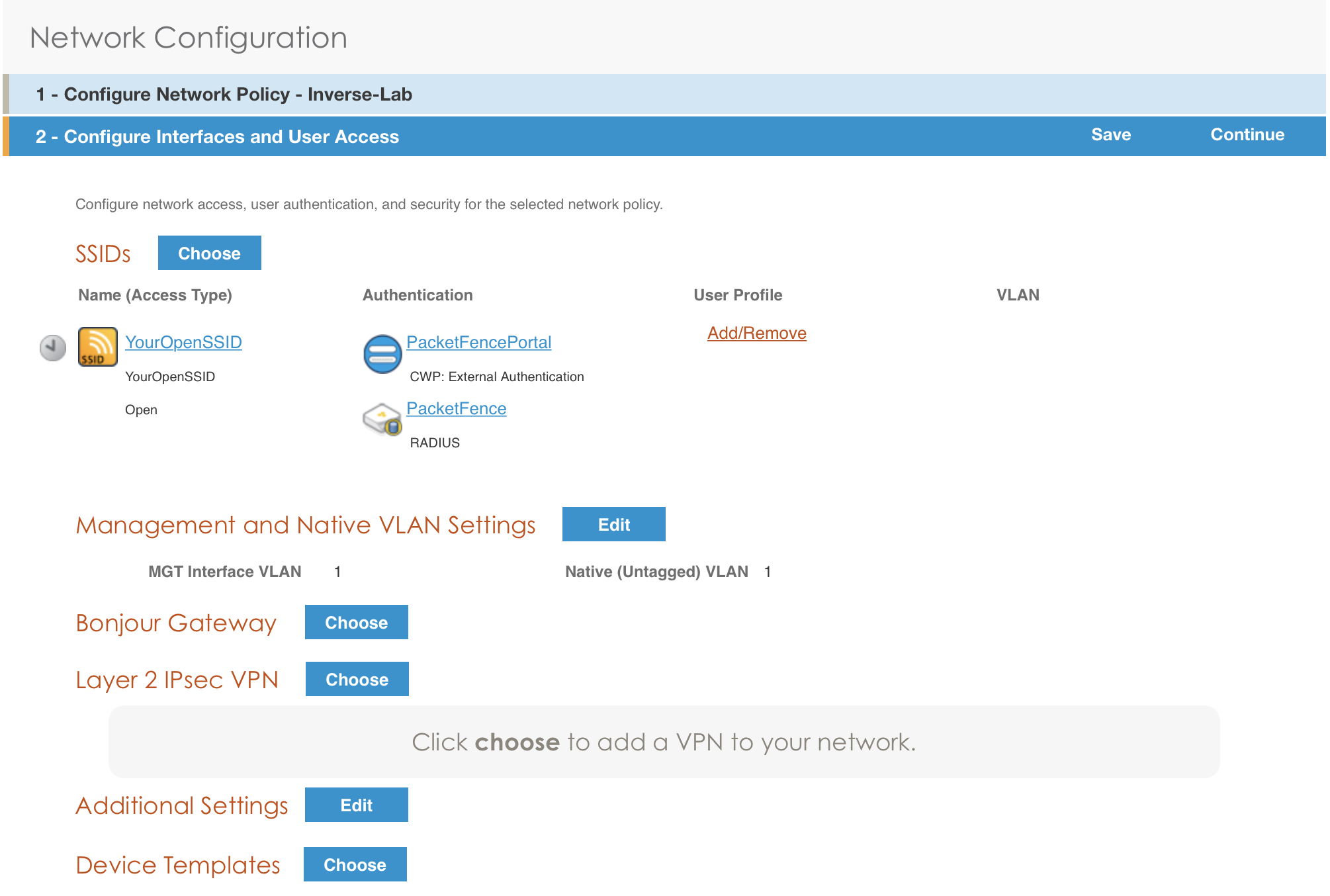
- under User Profile , click on Add/Remove and click on New
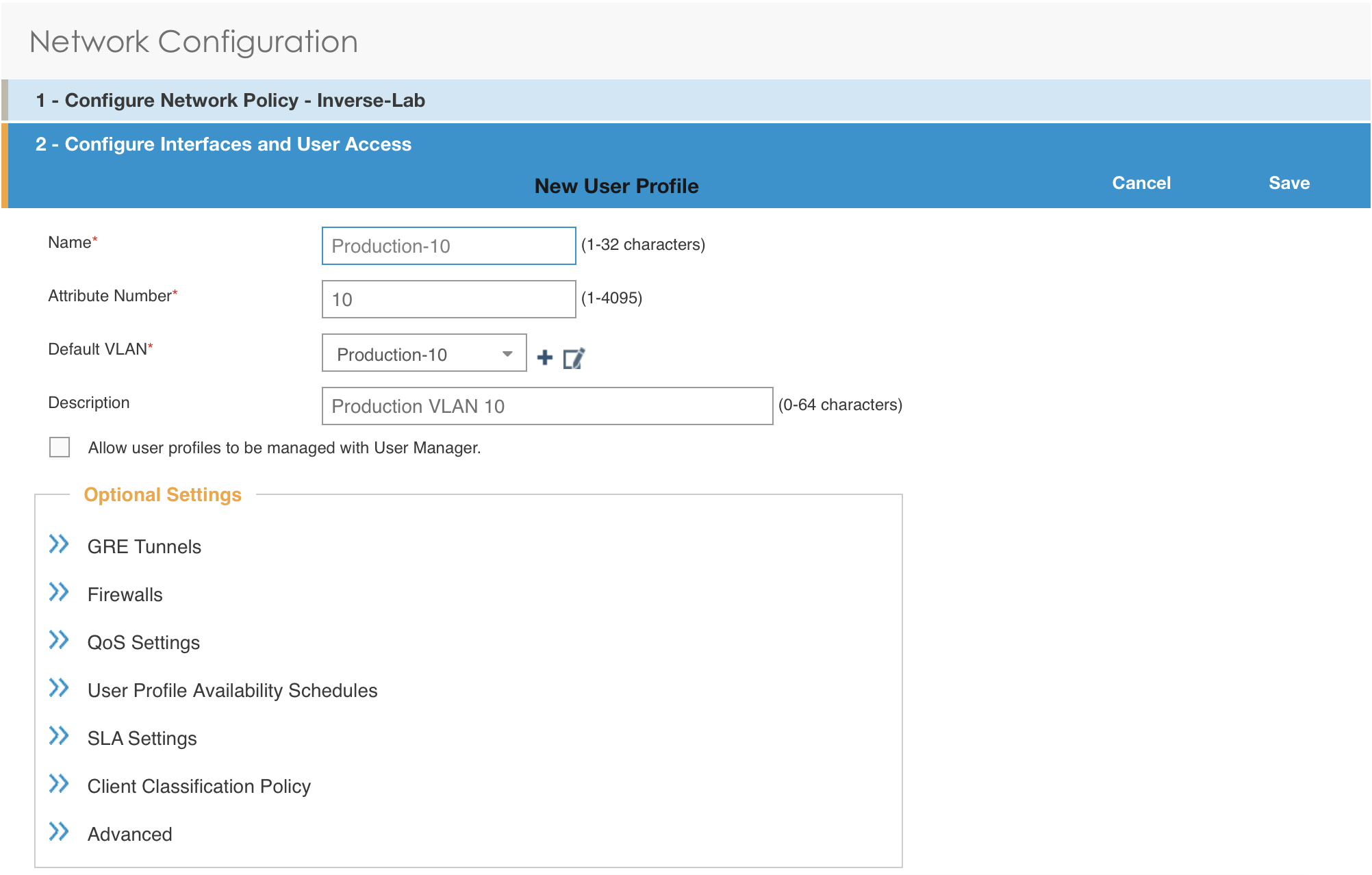
- enter the profile name, the VLAN ID and create the default VLAN as the same as the attribute number
- create a new default VLAN, click on the + button
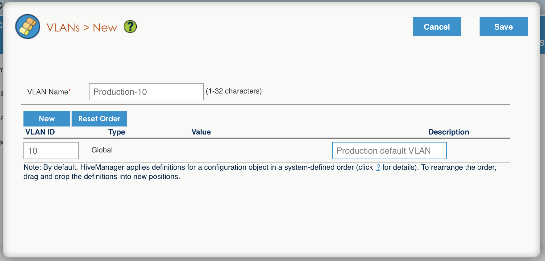
- click the Save button
- make sure the new user profile name is selected and then Save
Push the configuration to the Access Point:
- click on Continue
- select the AP and click Update - Update Devices
- under Configuration: select Perform a complete configuration update for all selected devices
- under HiveOS: select Don’t upgrade
- click on Update
- wait until the AP is back online
Configure PacketFence
Configure the Production interface to send the Portal:
- go to Configuration → Network Configuration → Interfaces
- under Logical Name, click on your interface name,
- Additionnal listening daemon(s), Add portal
- click on SAVE
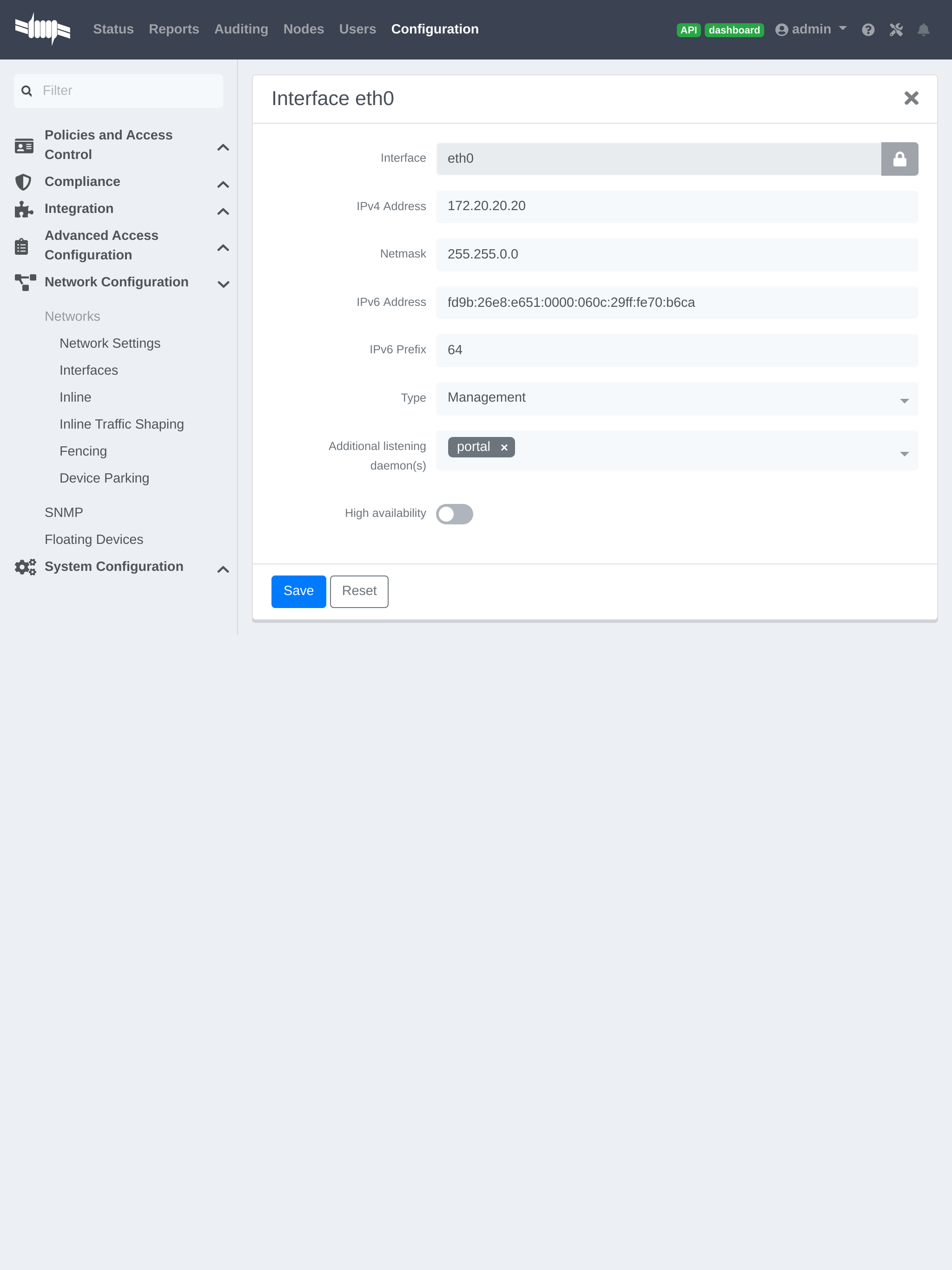
4.3.3. MAC Authentication/802.1X and Web Auth Configuration
In this case we want to be able to enable a MAC Authentication/802.1X and Web Auth SSID on the same wireless equipment. By default it’s not possible to provide a MAC Authentication/802.1X SSID and a Web Auth SSID with the same switch configuration, but by using the Switch Filters it will be possible to do it.
We will assume that we have an up and running SSID (YourSecuredSSID) already configured with Mac Authentication/802.1X:
-
from this documentation, we will assume that the VLANs tags are defined like following :
- PacketFence Management VLAN: 1 IP address: 192.168.1.5
- registration VLAN ID 2,subnet 192.168.2.0/24
- isolation VLAN ID 3, subnet 192.168.3.0/24
- production VLAN ID 10, subnet 172.16.1.0/24
Our SSID will be named YourOpenSSID, assuming that we want to provide a public Internet hotspot for example.
Add a New SSID
You should create a new SSID, has explained before, secured or open, as you need.
Configure Filters in PacketFence
Logon to your PacketFence server:
- Go to Configuration → Advanced Acccess Configuration → Filter Engines
- From the tab Switch filters,
- Go to the bottom of the configuration file and set the folllowing section.
[enable_external_portal_on_guest_ssid]status=enableddescription=enable_external_portal_on_guest_ssidscopes=radius_authorizeparam.0=ExternalPortalEnforcement=Ytop_op=andparam.1=VlanMap=Ncondition=ssid == "YourOpenSSID"
Click on SAVE.
4.3.4. Advanced Topics
Roles (User Profiles)
PacketFence supports user profiles on the Aerohive equipment. To build a User Profile, go to Configuration → User Profiles, and create what you need. When you define the switch definition in PacketFence, the role will match the User Profile attribute number. For example:
roles=CategoryStudent=1;CategoryStaff=2
And in the Aerohive configuration, you have:
StudentProfile attribute number 1StaffProfile attribute number 2
Last step is to allow the User Profile to be returned for a particular SSID. Go to Configuration → SSIDs → Your_SSID → User Profiles for Traffic Management, and select the User Profiles you will return for the devices.
In version 6 or later of the HiveOS, we do return VLAN ID matching the number that the User Profile has. Create your User Profile in the HiveManager as usual, assign the matching VLAN, and in PacketFence configuration add the wanted VLAN ID in the section Roles by VLAN.
Roles (User Profiles)
Since PacketFence 3.3, we now support user profiles on the AeroHIVE hardware. To build a User Profile, go to Configuration → User Profiles, and create what you need. When you define the switch definition in PacketFence, the role will match the User Profile attribute number. Example
roles=CategoryStudent=1;CategoryStaff=2
And in the AeroHIVE configuration, you have :
StudentProfile attribute number 1StaffProfile attribute number 2
Last step is to allow the User Profile to be returned for a particular SSID. Go to Configuration → SSIDs → Your_SSID → User Profiles for Traffic Management*, and select the User Profiles you will return for the devices.
In version 6 or later of the HiveOS, we do return VLAN ID matching the number that the User Profile has. Create your User Profile in the HiveManager as usual, assign the matching VLAN, and in PacketFence configuration add the wanted VLAN ID in the section Roles by VLAN.
4.4. Anyfi Networks
This section will discuss about the configuration of your Anyfi Gateway and Controller in order to use it with our configured PacketFence environment.
4.4.1. Deploy Anyfi Controller and Gateway
First thing, you will need to deploy the Anyfi Gateway and Controller on your network and configure basic connectivity between both of them.
When installing the Anyfi Gateway, have one interface in trunk mode for the
packet bridge. In this example it will be eth2 which is the last card on the
machine.
4.4.2. Anyfi Gateway Basic Configuration
Connect to the gateway using SSH and enter configuration mode. Now you need to add the configuration for `br0 which will link the access point traffic to your network.
interfaces {bridge br0 {aging 300hello-time 2max-age 20priority 0stp false}}
In this example eth1 will be the management interface of the Anyfi Gateway and
eth2 will be the interface that will contain the outbound WiFi traffic.
interfaces {ethernet eth1 {address <your management ip address>/<mask>duplex autosmp_affinity autospeed auto}ethernet eth2 {bridge-group {bridge br0}duplex autosmp_affinity autospeed auto}}
4.4.3. Open SSID Configuration
Still in configuration mode, configure the RADIUS server and SSID security.
service {anyfi {gateway ma-gw {accounting {radius-server <Management IP of PacketFence> {port 1813secret useStrongerSecret}}authorization {radius-server <Management IP of PacketFence> {port 1812secret useStrongerSecret}}bridge br0controller <IP or FQDN of the Anyfi Controller>isolationnas {identifier anyfiport 3799}ssid DemoOpen}}
4.4.4. Secure SSID Configuration
Still in configuration mode, configure the Anyfi Gateway to broadcast a WPA2 enterprise SSID.
service {anyfi{gateway secure-gw {authentication {eap {radius-server <Management IP of PacketFence> {port 1812secret useStrongerSecret}}}bridge br0controller <IP or FQDN of the Anyfi Controller>isolationssid DemoSecurewpa2 {}}}}
4.4.5. Deploy Access Point
You will now need to install CarrierWRT on a compatible access point and configure the Anyfi Controller in it. Depending on the access point you’re using, the method to install CarrierWRT will vary. For specifics about the CarrierWRT installation, refer to Anyfi’s documentation. Once this step is done, the SSID should be broadcasted.
4.5. Avaya
4.5.1. Wireless Controller
4.6. Aruba
4.6.1. All Aruba OS
Basic Aruba wireless controller configuration for PacketFence via the controller web interface. Tested on Aruba Controller 200 (ArubaOS 5.0.3.3) and Controller 600 (ArubaOS 6.0) - applies to all Aruba models.
AAA Settings
In the Web interface, go to Configuration → Authentication → RADIUS Server and add a RADIUS server named "packetfence" then edit it:
- Set Host to PacketFence’s IP (192.168.1.5)
- Set the Key to your RADIUS shared secret (useStrongerSecret)
- Click Apply
Under Configuration → Authentication → Server Group add a new Server Group named "packetfence" then edit it to add your RADIUS Server "packetfence" to the group. Click Apply.
Under Configuration → Authentication → RFC3576 add a new server with PacketFence’s IP (192.168.1.5) and your RADIUS shared secret (useStrongerSecret). Click Apply. Under Configuration → Authentication → L2 Authentication edit the MAC Authentication Profile called "default" then edit it to change the Delimiter to dash. Click Apply.
Under Configuration → Authentication → L2 Authentication edit the 802.1X Authentication Profile called "default" then edit it to uncheck the Opportunistic Key Caching under Advanced. Click Apply.
Under Configuration → Authentication → AAA Profiles click on the "default-mac-auth" profile then click on MAC Authentication Server Group and choose the "packetfence" server group. Click Apply. Move to the RFC3576 server sub item and choose PacketFence’s IP (192.168.1.5) click add then apply.
Under Configuration → Authentication → AAA Profiles click on the "default-dot1x" profile then click on 802.1X Authentication Server Group and choose the "packetfence" server group. Click Apply. Move to the RFC3576 server sub item and choose PacketFence’s IP (192.168.1.5) click add then apply.
Public SSID
In the Web interface, go to Configuration → AP Configuration then edit the "default" AP Group. Go in Wireless LAN → Virtual AP create a new profile with the following:
- AAA Profile: default-mac-auth
- SSID Profile: Select NEW then add an SSID (PacketFence-Public) and Network authentication set to None
Secure SSID
In the Web interface, go to Configuration → AP Configuration then edit the "default" AP Group. Go in Wireless LAN → Virtual AP create a new profile with the following:
- AAA Profile: default-dot1x
- SSID Profile: Select NEW then add an SSID (PacketFence-Secure) and Network authentication set to WPA2
Roles
Since PacketFence 3.3, we now support roles for the Aruba hardware. To add roles, go in Configuration → Access Control → User Roles → Add. You don’t need to force a VLAN usage in the Role since we send also the VLAN ID along with the Aruba User Role in the RADIUS request. Refer to the Aruba User Guide for more information about the Role creation.
WIPS
In order to use the WIPS feature in PacketFence, please follow those simple steps to send the traps to PacketFence.
First, configure PacketFence to be a trap receiver. Under Configuration → SNMP → Trap Receivers, add an entry for the PF management IP. By default, all traps will be enabled. If you want to disable some, you will need to connect via CLI, and run the snmp-server trap disable <trapname> command.
WebAuth
First of all you will need to configure a guest VLAN.
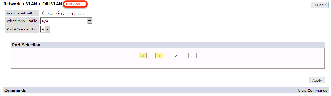
Next, you will need to configure a RADIUS server.
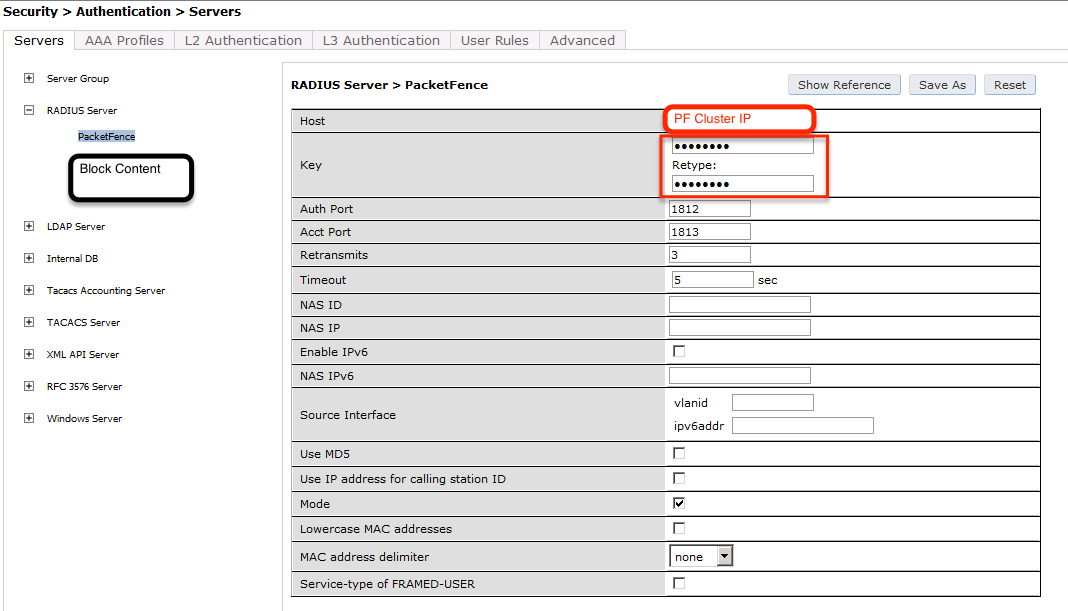
aaa authentication-server radius "packetfence"host 192.168.1.5key useStrongerSecret
Add your RADIUS server to a AAA group, under Security → Authentication → Servers → Server Group:
aaa server-group "packetfence"auth-server "packetfence" position 1
Then define the RFC 3576 server, which will allow you to do CoA.
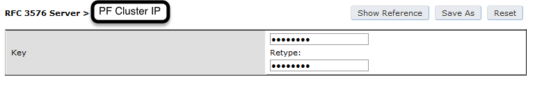
aaa rfc-3576-server "192.168.1.5"key useStrongerSecret
Next, you will need to create the policy that will redirect users to the PacketFence captive portal when they are not authenticated. Go to Security → Authentication → L3 Authentication → Captive Portal Authentication Profile.
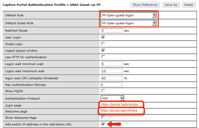
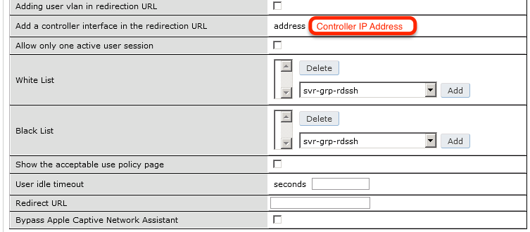
aaa authentication captive-portal "packetfence-externalportal"default-role auth-guestredirect-pause 3no logout-popup-windowlogin-page https://192.168.1.5/Arubaswitchip-in-redirection-url
Now create the policy for the guest access, for example Internet only.
Add the authentication for the Captive Portal Profile via Security → Authentication → L3 Authentication → Captive Portal Authentication Profile → Server Group:
aaa authentication captive-portal "packetfence-externalportal"server-group "packetfence"
Adjust the configuration of the AAA profile through Security → Authentication → Profiles → AAA Profiles:
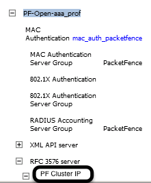
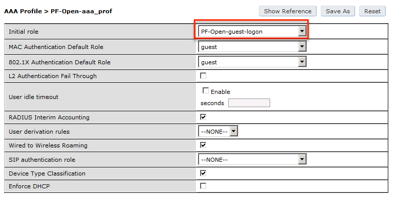
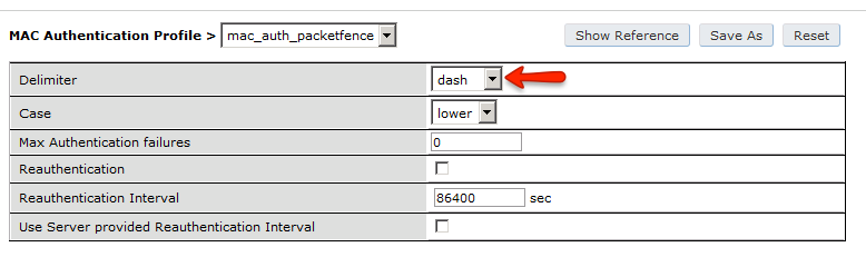
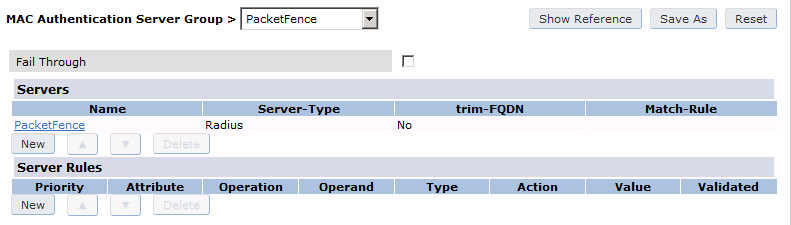
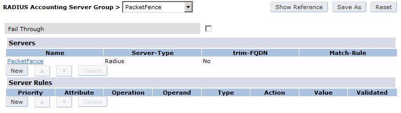
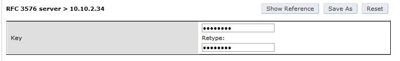
aaa profile "packetfence-externalportal"initial-role packetfence-portalradius-interim-accountingradius-accounting "packetfence"rfc-3576-server "192.168.1.5"
Define a policy to permit the traffic.
First add a destination, Advanced Services → Stateful Firewall → Destinations:
netdestination packetfence-portalhost 192.168.1.5
Create an ACL for the redirection, Security → Firewall Policies:
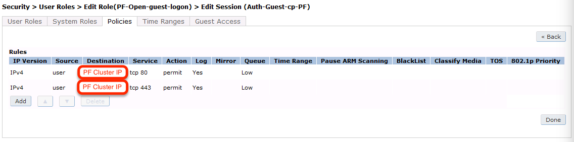
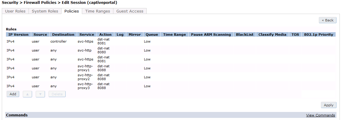
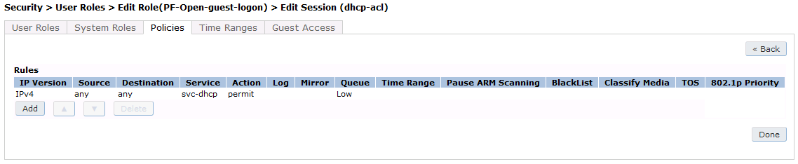
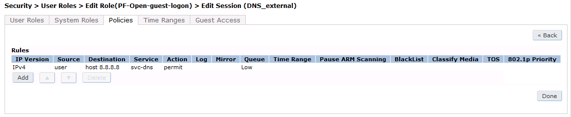
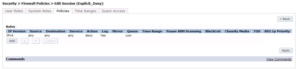
Source NAT on VLAN
ip access-list session "packetfence-externalportal"alias "user" alias "packetfence-portal" "svc-http" permit queue lowalias "user" alias "packetfence-portal" "svc-https" permit queue low
Enable the "firewall allow-tri-session" :
firewall allow-tri-session
Source NAT per Application
ip access-list session "packetfence-externalportal"alias "user" alias "packetfence-portal" "svc-http" src-nat queue lowalias "user" alias "packetfence-portal" "svc-https" src-nat queue low
Now add the newly created policy to the Captive Portal Profile, Security → User Roles:
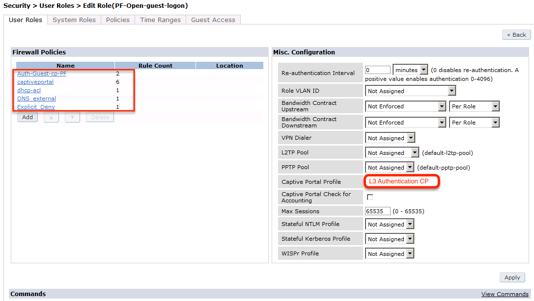
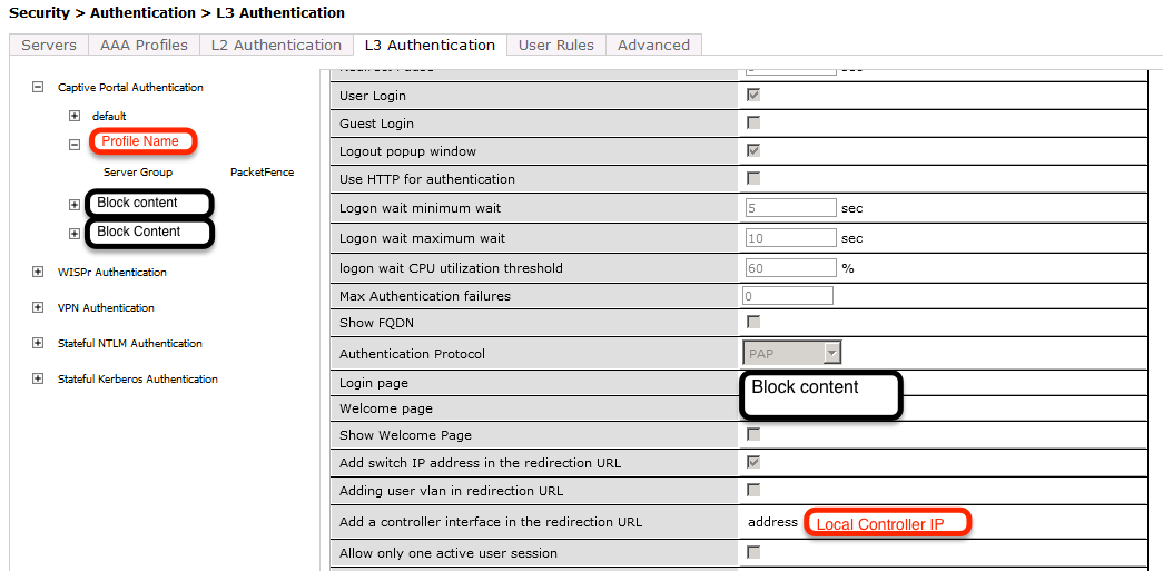
user-role "packetfence-portal"access-list session "packetfence-externalportal" position 1access-list session "captiveportal" position 2access-list session "guest-logon-access" position 3access-list session "block-internal-access" position 4access-list session "v6-logon-control" position 5access-list session "captiveportal6" position 6captive-portal "packetfence-externalportal"
Finaly create the SSID and associate the profile to it, Virtual AP profile:
wlan virtual-ap "packetfence-externalportal"ssid-profile "packetfence-externalportal"aaa-profile "packetfence"
General AP settings and master-slave controller case.
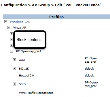
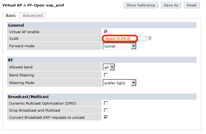
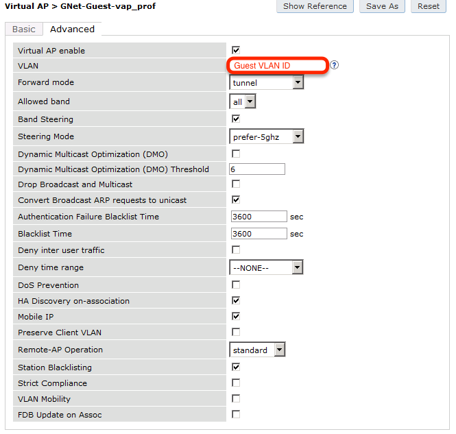
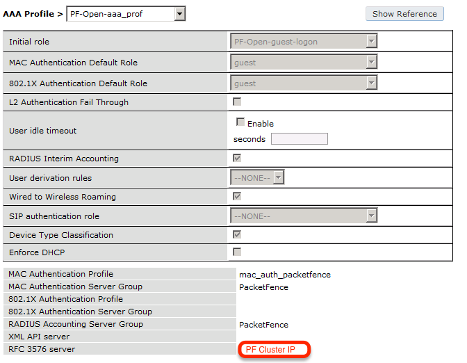
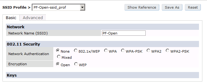
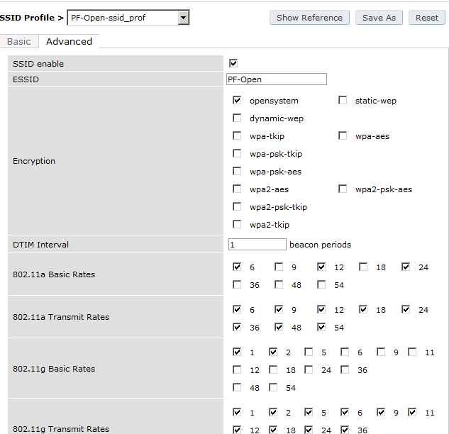
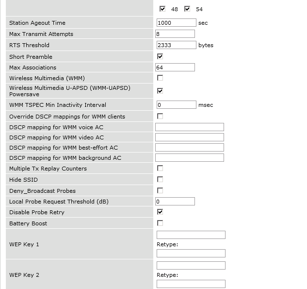
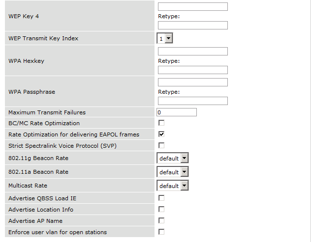
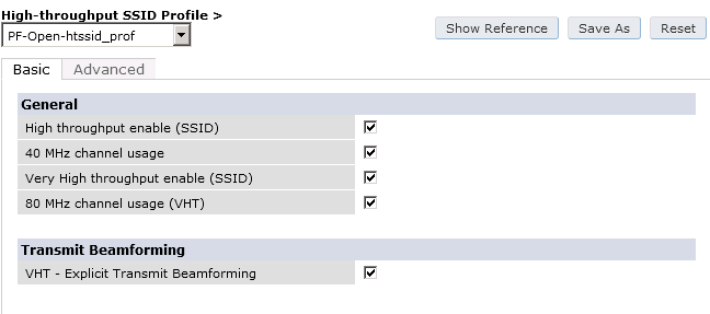
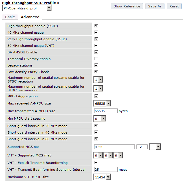
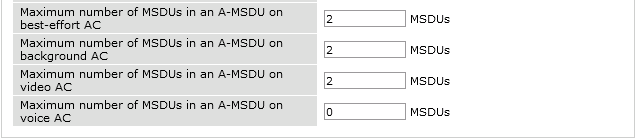
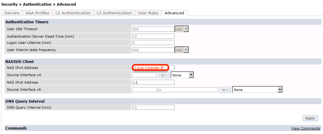
The next step will be to configure the Aruba WiFi controller for WebAuth in
PacketFence, add the switch with the model choice Aruba Network,
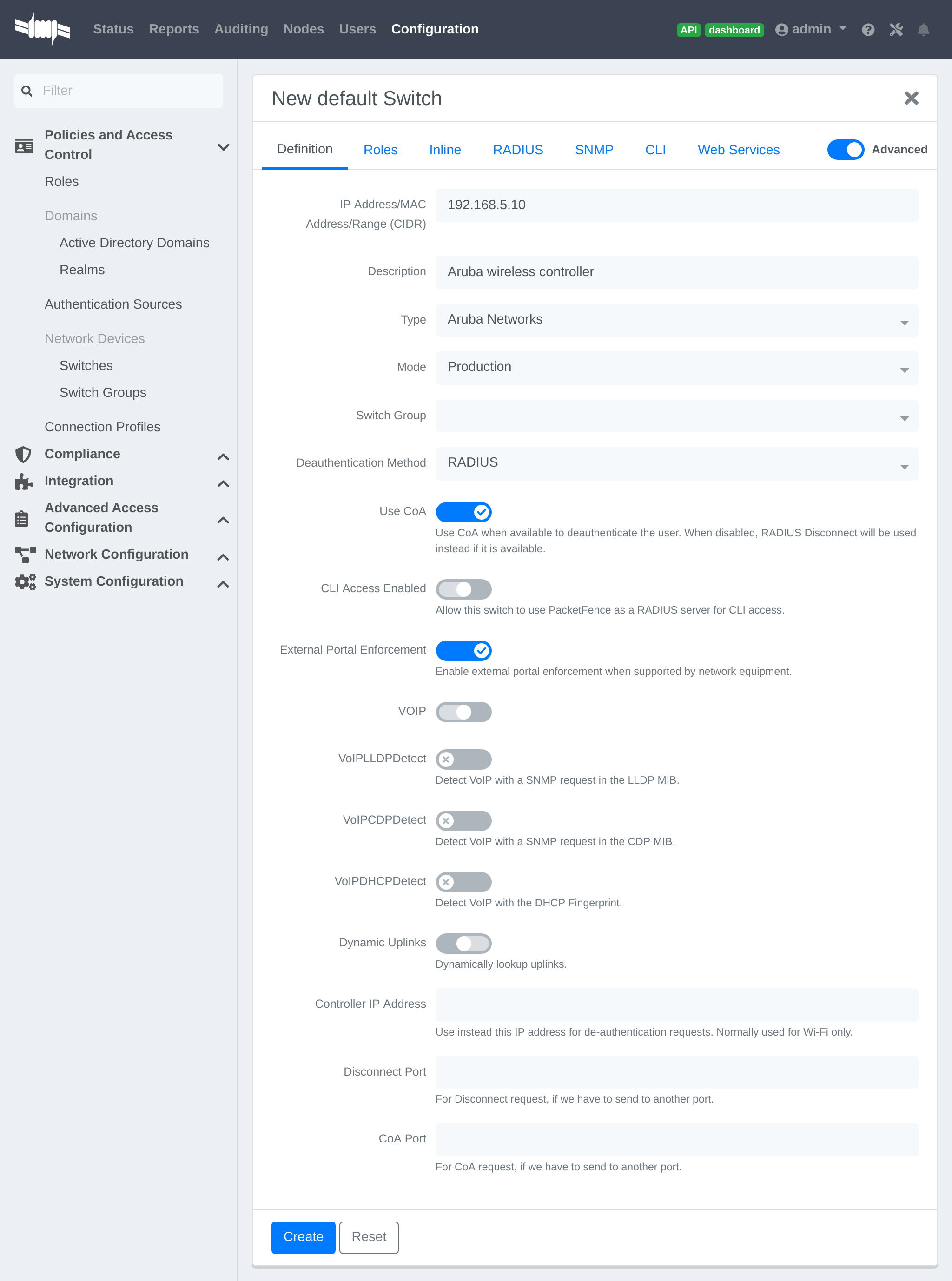
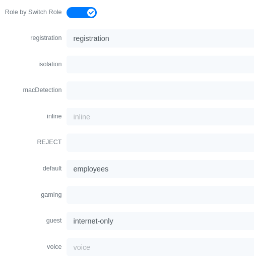
Check the box External Portal Enforcement, in the Roles section, choose Role
by Switch Role, as the registration role, enter your default role:
packetfence-portal and choose the policy matching roles, for instance guest:
internet-only.
CLI authentication
In order to enable CLI login on the Aruba controller via the PacketFence server, you need to point management authentication to the RADIUS server you created while configuring the SSIDs in the previous sections above.
aaa authentication mgmt default-role read-only enable server-group PacketFence
4.6.2. Aruba Controller 200
In this section, we cover the basic configuration of the Aruba Controller 200 for PacketFence using the command line interface. We suggest you use the instructions above for the controller web interface instead.
VLAN definition
Here, we create our PacketFence VLANs, and our AccessPoint VLAN (VID 66). It is recommended to isolate the management of the thin APs in a separate VLAN.
vlan 2vlan 3vlan 5vlan 10vlan 66
AAA Authentication Server
aaa authentication-server radius "PacketFence"host 192.168.1.5key useStrongerSecretaaa server-group "Radius-Group"auth-server PacketFence
AAA Profiles
aaa profile "default-dot1x"authentication-dot1x "default"dot1x-default-role "authenticated"dot1x-server-group "Radius-Group"radius-accounting "Radius-Group"aaa profile "PacketFence"authentication-mac "pf_mac_auth"mac-server-group "Radius-Group"radius-accounting "Radius-Group"
WLAN SSIDs: profiles and virtual AP
wlan ssid-profile "PacketFence-Public"essid "PacketFence-Public"wlan ssid-profile "PacketFence-Secure"essid "PacketFence-Secure"opmode wpa2-aeswlan virtual-ap "Inverse-Guest"aaa-profile "PacketFence"ssid-profile "PacketFence-Public"wlan virtual-ap "Inverse-Secure"aaa-profile "default-dot1x"ssid-profile "PacketFence-Secure"ap-group "Inverse"virtual-ap "Inverse-Guest"virtual-ap "Inverse-Secure"ids-profile "ids-disabled"
4.6.3. All Aruba Instant OS
Add your packetfence instance to your configuration:
wlan auth-server packetfence
ip 192.168.1.5port 1812acctport 1813timeout 10retry-count 5key useStrongerSecretnas-ip [Aruba Virtual Controller IP]rfc3576
Add dynamic vlan rules and mac auth to your ssid profile:
wlan ssid-profile SSID
index 0type employeeessid ESSIDwpa-passphrase WPA-Passphraseopmode wpa2-psk-aesmax-authentication-failures 0vlan 1auth-server packetfenceset-vlan Tunnel-Private-Group-Id contains 1 1set-vlan Tunnel-Private-Group-Id contains 4 4rf-band allcaptive-portal disablemac-authenticationdtim-period 1inactivity-timeout 1000broadcast-filter noneradius-reauth-interval 5dmo-channel-utilization-threshold 90
4.7. Belair Networks (now Ericsson)
4.7.1. BE20
The Belair Networks BE20s are fairly easy to configure.
Add VLANs
On the BE20 Web Interface, click on Eth-1-1. By default, there will be nothing in there. You need to first create an untagged VLAN (VLAN 0). In order to do that, you need to set the PVID, Reverse PVID, and the VLAN field to 0. Then click add.
Repeat that step for each of your VLANs by entering the proper VLAN ID in the VLAN field.
AAA Servers
Once you have the VLANs setup, you need to add PacketFence into the AAA Server list. Go to System → Radius Servers. Click on Add server, and fill out the proper information.
- Ensure the Enabled checkbox is selected
- IP Address: Insert the IP Address of the PacketFence Management Interface
- Shared Secret: Insert the shared secret for RADIUS communication
When done, click on the Apply button.
Secure SSID
Since the BE20 doesn’t support Open SSID with MAC Authentication, we will only describe how to configure a WPA2-Enterprise SSID. First, we will configure the 5GHz antenna.
Click on Wifi-1-1 → Access SSID Config. From the Configuration for SSID dropdown, select the 1 entry. Modify the fields like the following:
- SSID: Put your SSID Name you would like
- Type: Broadcast
- Use Privacy Mode: WPA2(AES) with EAP/DOT1x
- RADIUS NAS Identifier: You can put a string to identify your AP
- Radius Accounting Enabled: Checkbox Selected
- Radius Station ID Delimiter: dash
- Radius StationId Append Ssid: Checkbox Selected
- RADIUS Server 1: Select the AAA Server you created earlier
When done click Apply. Repeat the same configuration for the 2.4GHz Antenna (Wifi-1-2).
That should conclude the configuration. You can now save the configs to the flash by hitting the Config Save button on top of the Interface.
4.8. Bluesocket
4.8.1. MAC Authentication
Bluesocket side
In order to configure mac authentication on the Bluesocket, you must have access to the controller.
First, you must configure a RadiusWebAuthServer in External Authentication and enable "Enable Radius MAC Authentication" and add Authentications rules.
This Authentication Rules needs to match with the PacketFence role you define.
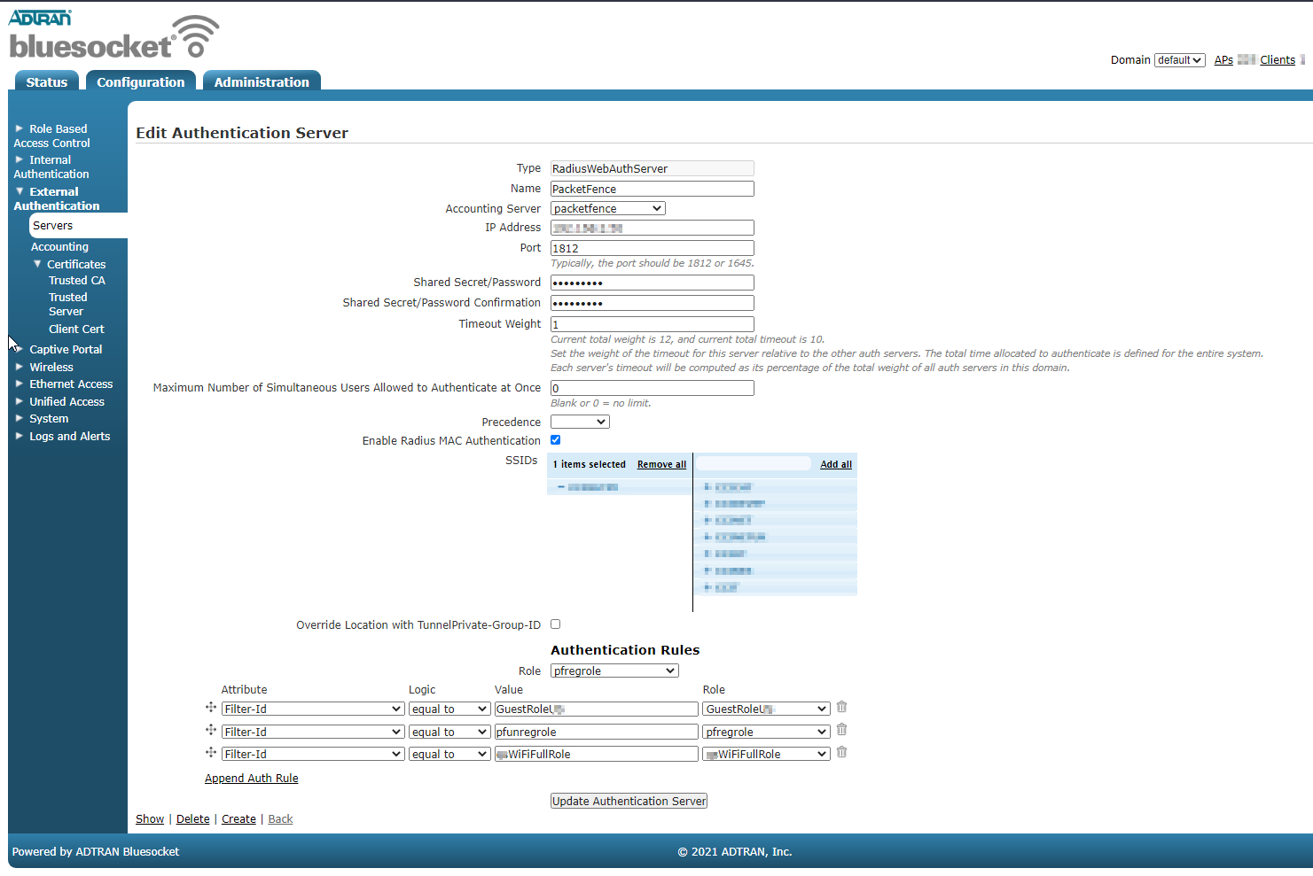
Next, you need to create an SSID in Wireless → SSIDs and important, check for "Enable Captive Portal Authentication".
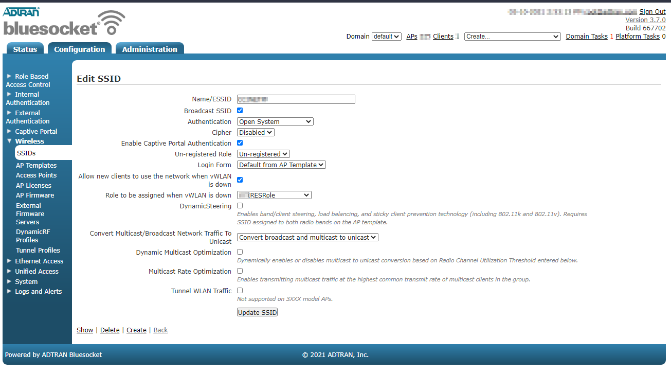
PacketFence side
You have to define the ip address of the Blusocket controller in PacketFence.
Since the vlan assignation is made by role, you need to enable role by switch role and define the role you previously created in the Bluesocket "Authentications rules".
For the deauthentication you need to select HTTPS and fill the Web Services section with the username and password to connect to the Bluesocket API.
4.8.2. 802.1x
First, you must configure a Radius1XAuthServer in External Authentication.
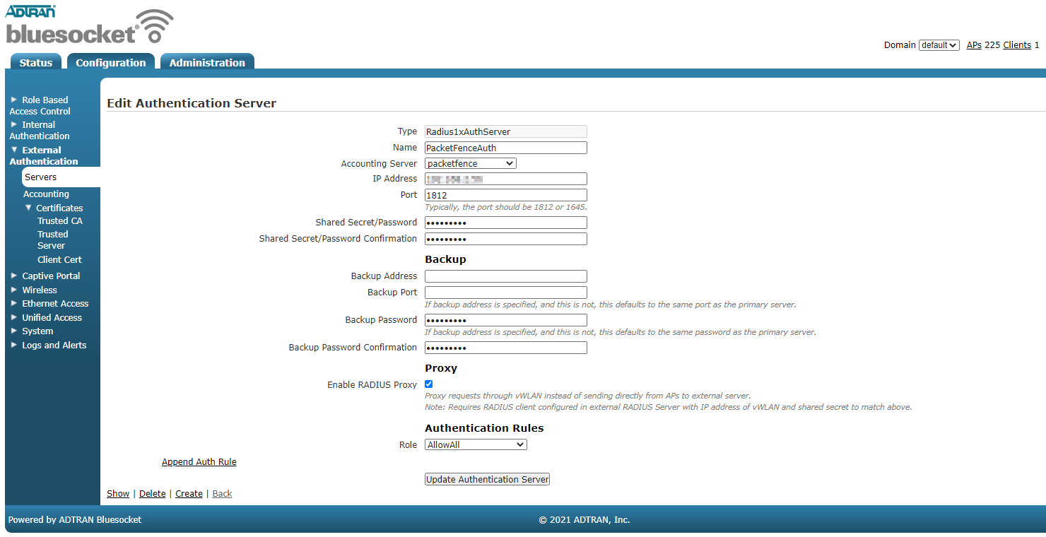
Next you need to create a new SSID with AUthentication WPA+WPA2 and select the radius server you previously created as the "RADIUS 802.1x Authentication Server"
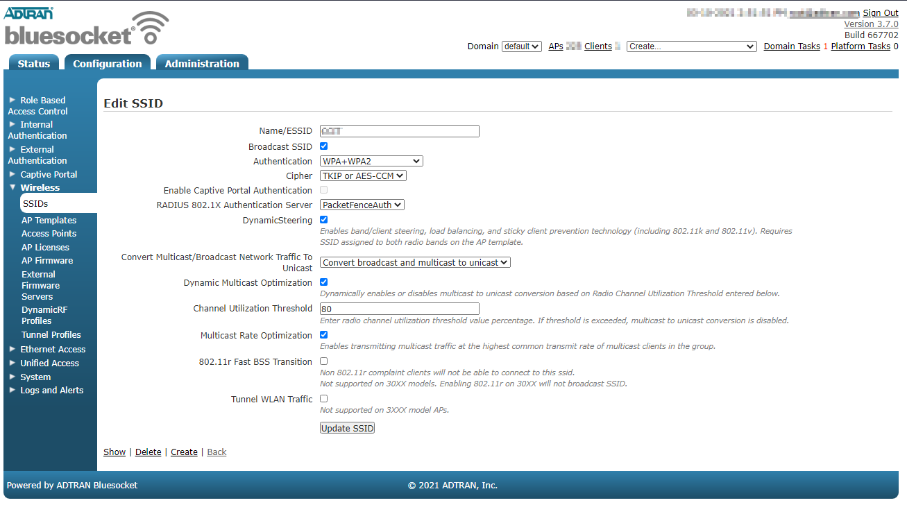
PacketFence side
You have to define the ip address of the Bluesocket controller in PacketFence.
Since the vlan assignation is made by role, you need to enable role by switch role and define the role you that exist in the Bluesocket.
For the deauthentication you need to select HTTPS and fill the Web Services section with the username and password to connect to the Bluesocket API.
4.9. Brocade
4.9.1. RF Switches
See the Motorola RF Switches documentation.
4.10. Cambium
4.10.1. cnPilot E410
802.1X
To setup the Cambium cnPilot E410 AP to use 802.1x, first, you need to already have configured the VLANs that will be used in the AP under Configure → Network. Make sure that in Configure → Network → Ethernet Ports, the port is configured to Trunk Multiple VLANs, and the list of VLANs are allowed.
Next, go to Configure → WLAN, and click on Add New WLAN. Give it the
desired ID, and enter your SSID, default VLAN, and select WPA2 Enterprise for
Security.
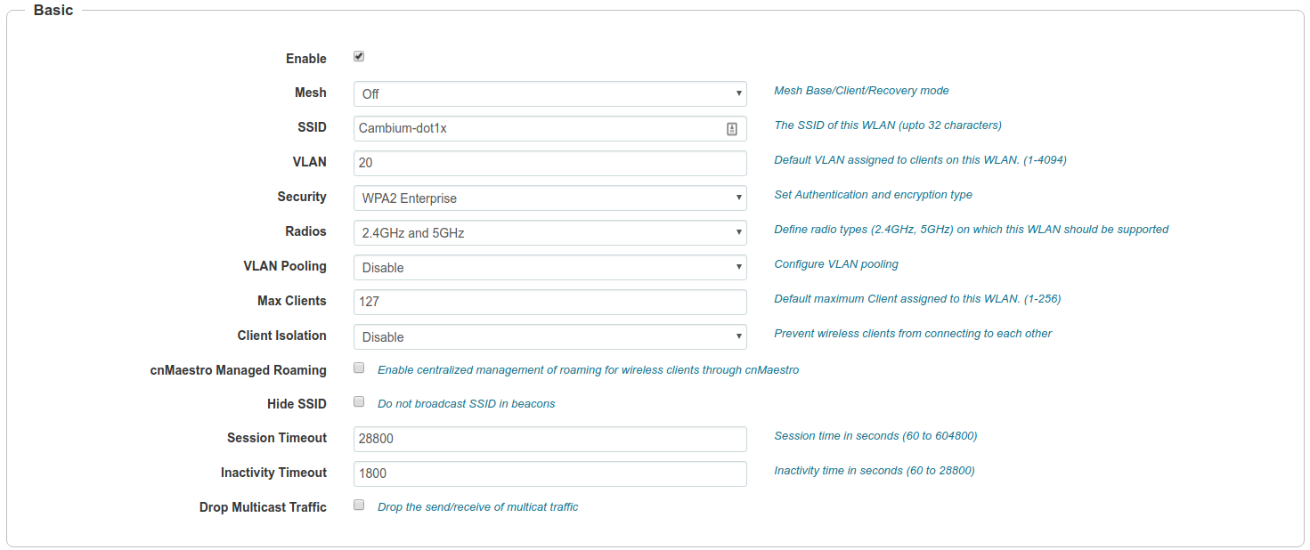
In the *RADIUS Server_ tab, enter the management IP address of PacketFence (VIP in case of a cluster) and the Radius secret for Authentication and Accounting servers.
Check the Dynamic Authorization and Dynamic VLAN boxes and save.
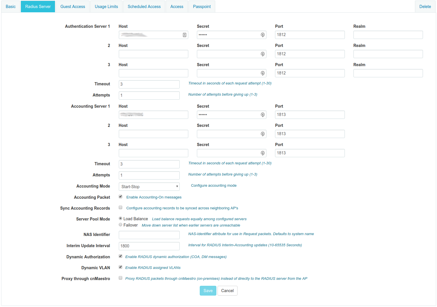
MAC Authentication
To enable MAC authentication in the Cambium E410, go to Configure → WLAN, select your WLAN, set the Security to open and click on the tab Access.
In the MAC Authentication section, select Radius as the policy, and check the box for Password to use the MAC address as the password in the Radius request. Click on Save.
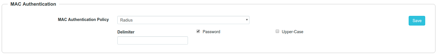
Web Authentication
To enable Web Authentication, go to your WLAN in Configure → WLAN, create a new WLAN with open Security, and click on the tab Guest Access to set the following:
- Enable: check the box
- Portal Mode: External Hotspot
- Access Policy: Radius
- Redirect Mode: HTTP
- External Page URL: http://_IP_ADDRESS_OF_PACKETFENCE/Cambium
- External Portal Type: Standard
- Success Action: Your preferred action.
- Prefix Query Strings in Redirect URL: check the box
- Redirection URL Query String: check Client IP
- Redirect: check HTTP-only
Click Save.
In the Add Whitelist section, add the IP address or domain name of your PacketFence server, then save.
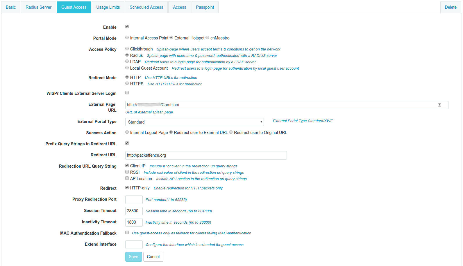
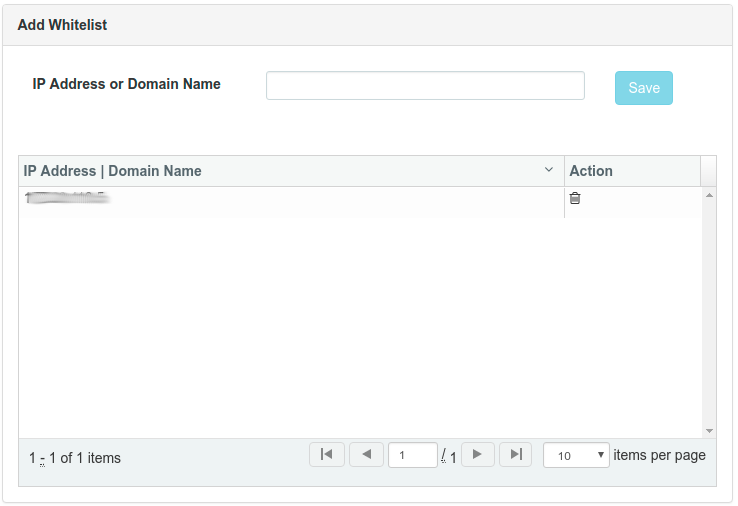
On PacketFence web admin, in the Switch configuration for your AP, Roles tab, check Role by Web Auth URL box, and enter http://_IP_ADDRESS_OF_PACKETFENCE/Cambium in the registration field.
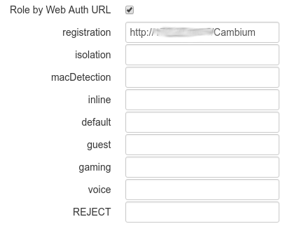
4.11. Cisco
4.11.1. Aironet 1121, 1130, 1242, 1250, 1600
MAC-Authentication + 802.1X configuration
Radio Interfaces:
dot11 vlan-name normal vlan 1dot11 vlan-name registration vlan 2dot11 vlan-name isolation vlan 3dot11 vlan-name guest vlan 5interface Dot11Radio0encryption vlan 1 mode ciphers aes-ccmencryption vlan 2 mode ciphers aes-ccmssid PacketFence-Publicssid PacketFence-Secureinterface Dot11Radio0.2encapsulation dot1Q 2no ip route-cachebridge-group 253bridge-group 253 subscriber-loop-controlbridge-group 253 block-unknown-sourceno bridge-group 253 source-learningno bridge-group 253 unicast-floodingbridge-group 253 spanning-disabledinterface Dot11Radio0.3encapsulation dot1Q 3no ip route-cachebridge-group 254bridge-group 254 subscriber-loop-controlbridge-group 254 block-unknown-sourceno bridge-group 254 source-learningno bridge-group 254 unicast-floodingbridge-group 254 spanning-disabledinterface Dot11Radio0.5encapsulation dot1Q 5no ip route-cachebridge-group 255bridge-group 255 subscriber-loop-controlbridge-group 255 block-unknown-sourceno bridge-group 255 source-learningno bridge-group 255 unicast-floodingbridge-group 255 spanning-disabled
LAN interfaces:
interface FastEthernet0.2encapsulation dot1Q 2no ip route-cachebridge-group 253no bridge-group 253 source-learningbridge-group 253 spanning-disabledinterface FastEthernet0.3encapsulation dot1Q 3no ip route-cachebridge-group 254no bridge-group 254 source-learningbridge-group 254 spanning-disabledinterface FastEthernet0.5encapsulation dot1Q 5no ip route-cachebridge-group 255no bridge-group 255 source-learningbridge-group 255 spanning-disabled
Then create the two SSIDs:
dot11 ssid PacketFence-Securevlan 3 backup normalauthentication open eap eap_methodsauthentication key-management wpadot11 ssid PacketFence-Publicvlan 2 backup guestauthentication open mac-address mac_methodsmbssid guest-mode
Configure the RADIUS server (we assume here that the FreeRADIUS server and the PacketFence server are located on the same box):
radius-server host 192.168.1.5 auth-port 1812 acct-port 1813 key useStrongerSecretaaa group server radius rad_eapserver 192.168.1.5 auth-port 1812 acct-port 1813aaa authentication login eap_methods group rad_eapaaa group server radius rad_macserver 192.168.1.5 auth-port 1812 acct-port 1813aaa authentication login mac_methods group rad_mac
4.11.2. Aironet 1600
CoA and radius:
radius-server attribute 32 include-in-access-req format %hradius-server vsa send accountingaaa server radius dynamic-authorclient 192.168.1.5server-key 7 useStrongerSecretport 3799auth-type all
4.11.3. Aironet (WDS)
To be contributed...
4.11.4. Wireless LAN Controller (AireOS)
In this section, we cover the basic configuration of the WLC for PacketFence using the WLC web interface.
- First, globally define the FreeRADIUS server running on PacketFence (PacketFence’s IP) and make sure Support for RFC 3576 (also called Support for CoA) is enabled. When the option is missing from your WLC, it is enabled by default.
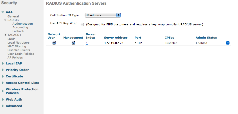
-
Then we create two SSIDs:
- PacketFence-Public: non-secure with MAC authentication only
- PacketFence-Secure: secure with WPA2 Enterprise PEAP/MSCHAPv2
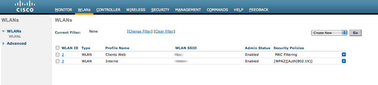
- In the secure SSID, make sure 802.1X is enabled and select the appropriate encryption for your needs (recommended: WPA + WPA2)
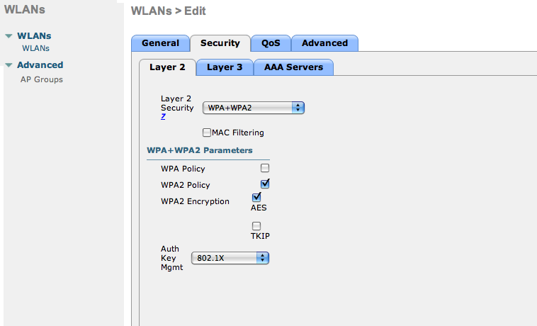
- No layer 3 security
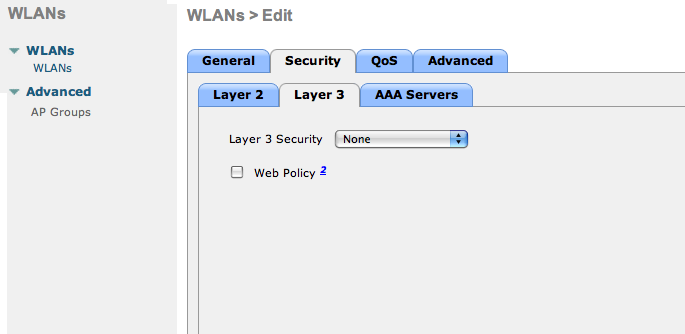
- We set the IP of the FreeRADIUS server
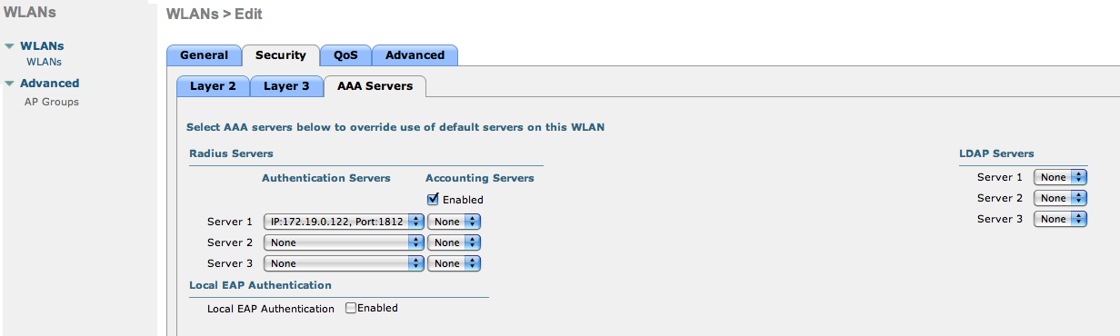
- VERY IMPORTANT: Allow AAA override (this allows VLAN assignment from RADIUS)
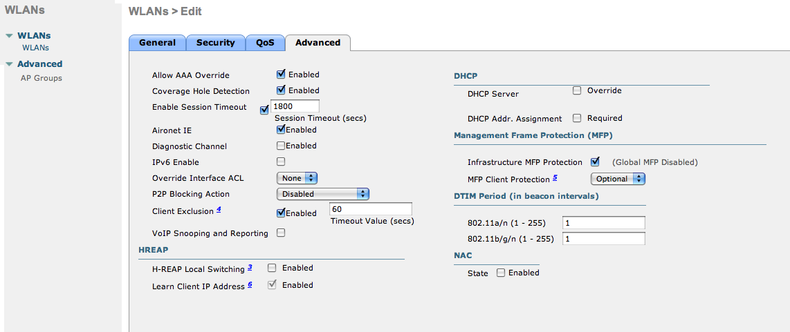
- Edit the non-secure SSID: Enable MAC authentication at level 2
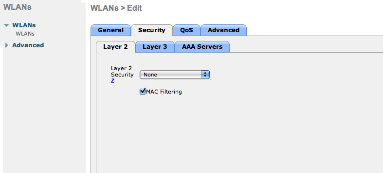
- Nothing at level 3
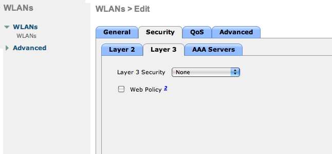
- We set the IP of the FreeRADIUS server
- VERY IMPORTANT: Allow AAA override (this allows VLAN assignment from RADIUS)
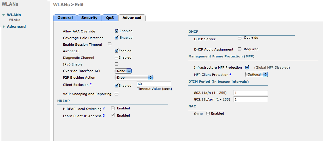
- Finally, in Controller → Interfaces tab, create an interface per VLAN that could be assigned
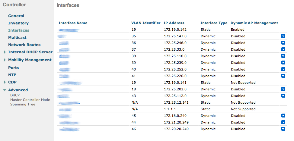
You are good to go!
Wireless LAN Controller (AireOS) Web Auth
In this section, we cover the basic configuration of the WLC AireOS Web Auth for PacketFence using the WLC web interface. The idea is to forward the device to the captive portal with an ACL if the device is in an unreg state and allow the device to reach Internet (or the normal network) by changing the ACL once registered. In the unreg state, the WLC will intercept the HTTP traffic and forward the device to the captive portal.
In this sample configuration, the captive portal uses the IP address 172.16.0.250, the management interface uses the IP address 172.16.0.249 and the WLC uses the IP address 172.16.0.248. The DHCP and DNS servers are not managed by PacketFence (WLC DHCP Server, Production DHCP Server)
- First, globally define the FreeRADIUS server running on PacketFence (PacketFence’s management interface) and make sure Support for RFC 3576 is enabled (if not present it is enabled by default)
-
Then we create a SSID:
- OPEN SSID: non-secure with MAC authentication only
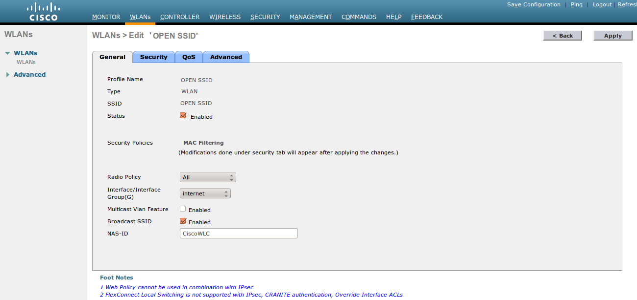
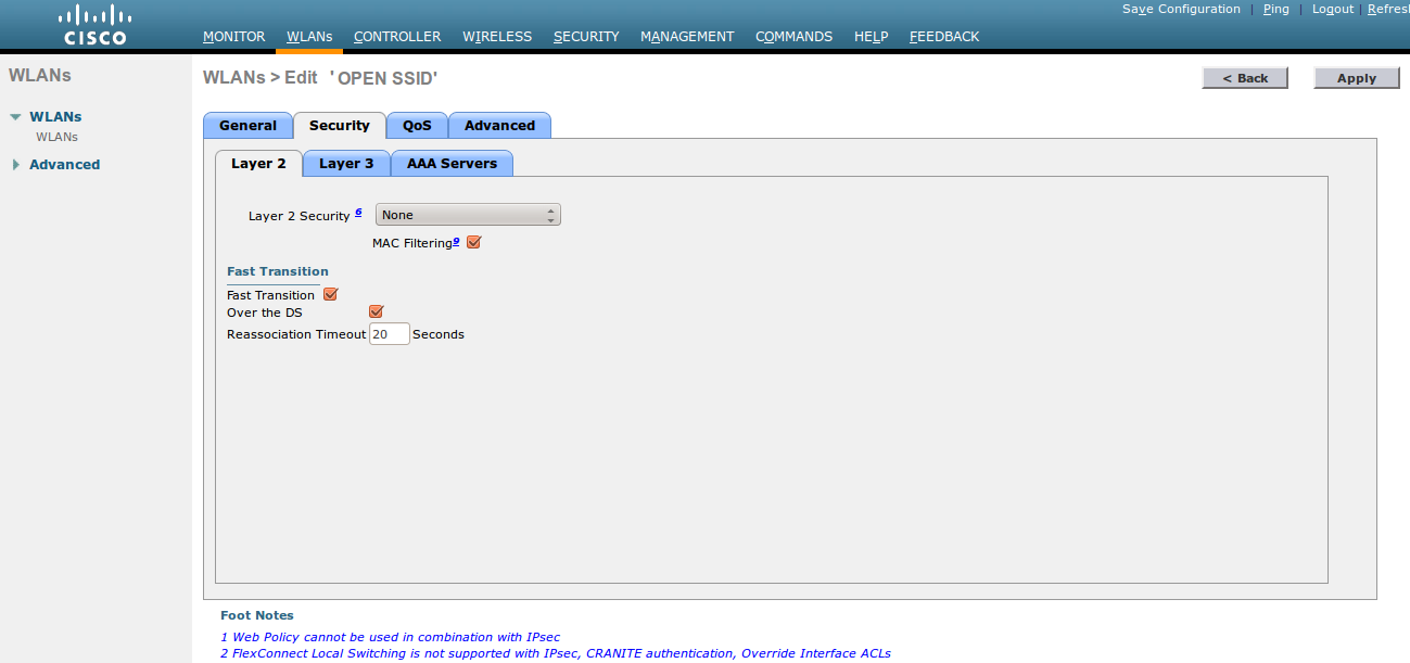
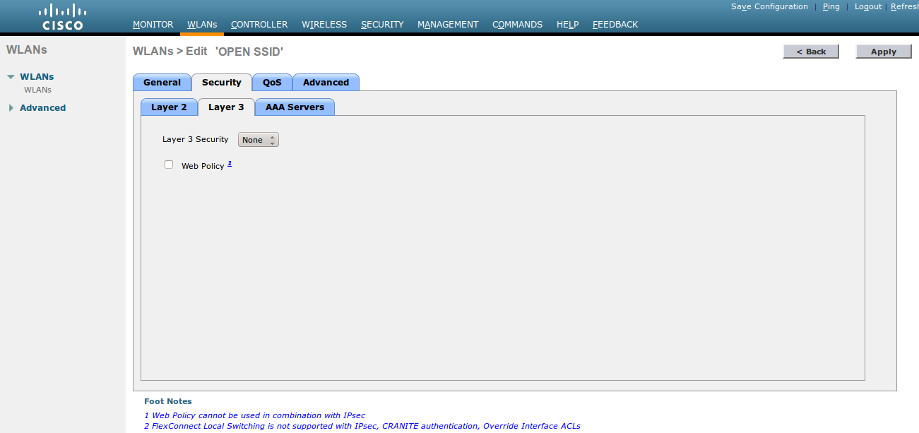
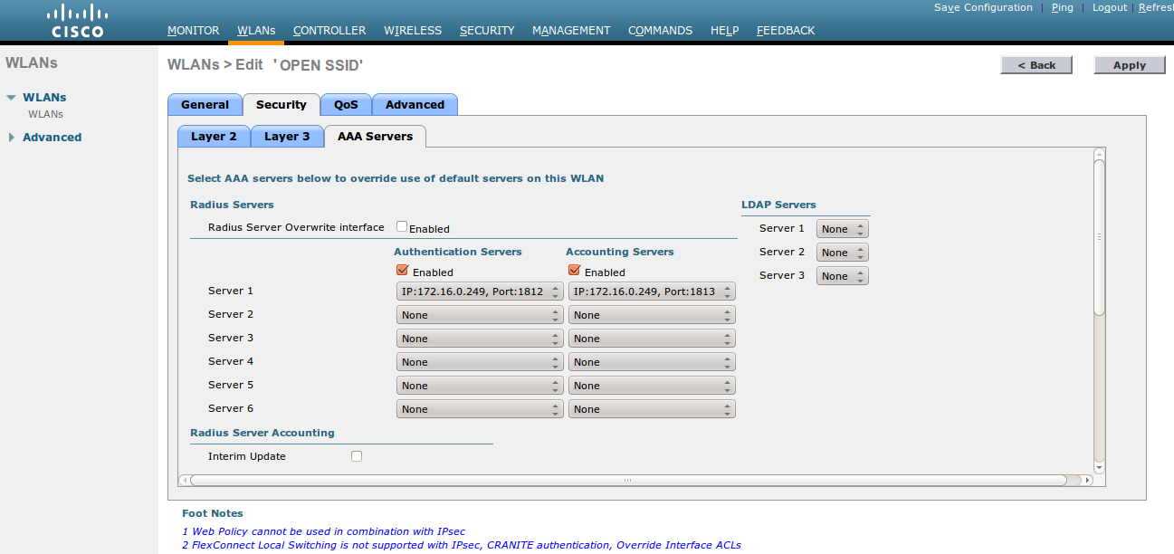
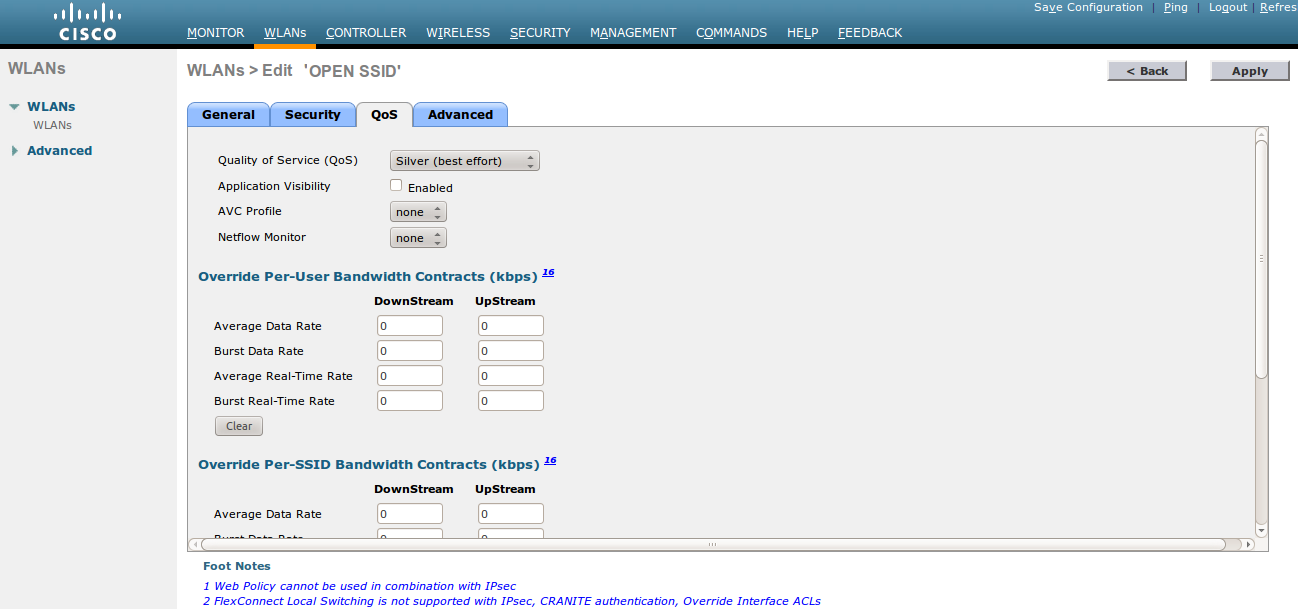
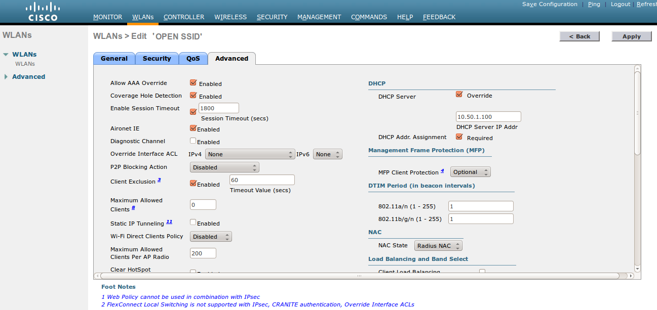
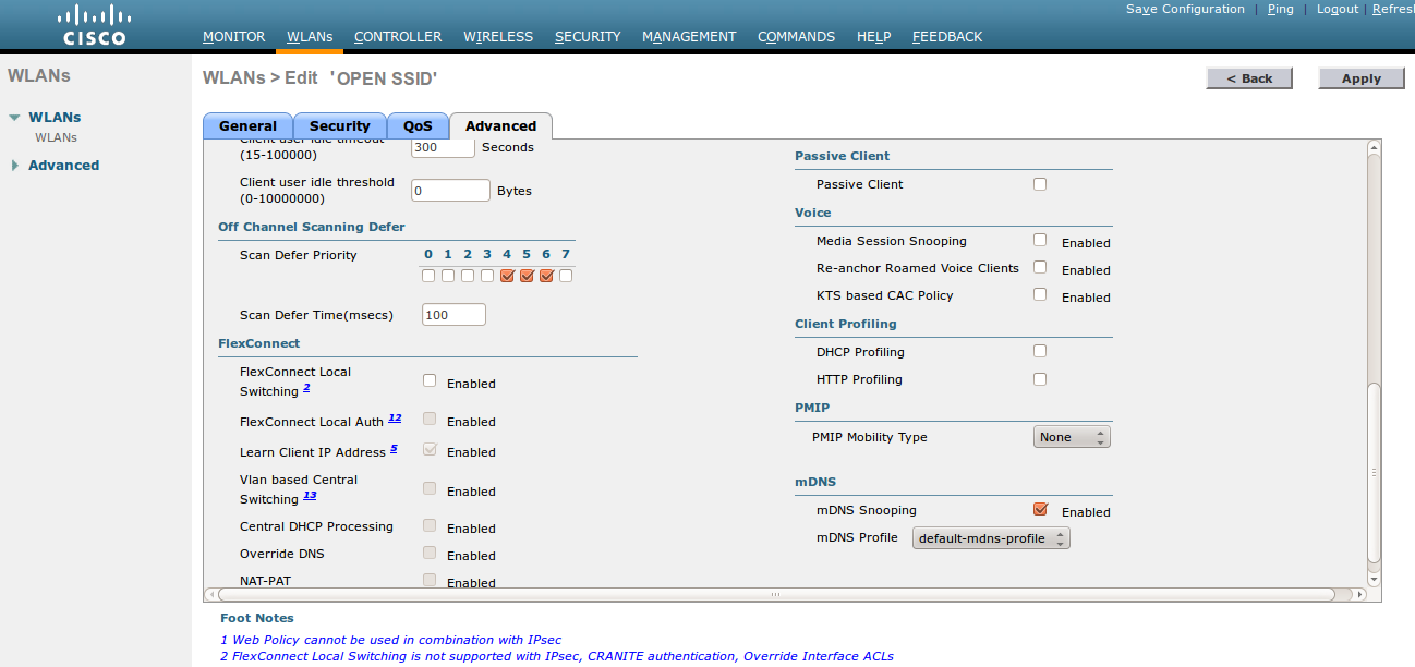
- Then you have to create two ACLs - one to deny all traffic except the required one to hit the portal (Pre-Auth-For-WebRedirect ) and the other one to allow anything (Authorize_any) .
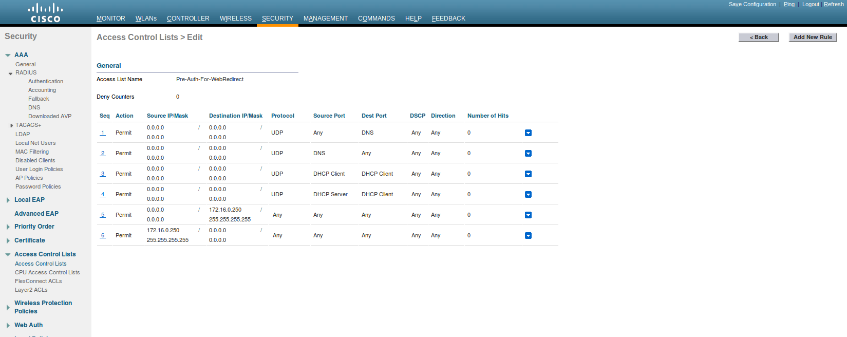
- Then the last step is to configure the WLC AireOS in PacketFence. Role by Web Auth URL
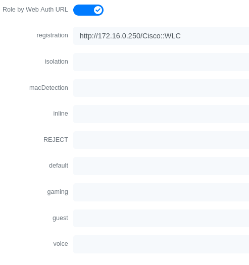
Role definition
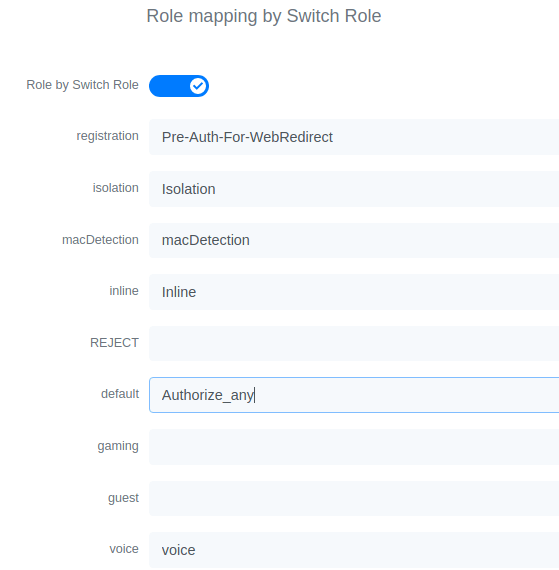
Wireless LAN Controller (AireOS) IPSK
In this section, we cover the basic configuration of the WLC AireOS IPSK feature. Starting from WLC AireOS 8.5 release, Cisco introduces the IPSK feature. Identity PSKs are unique pre-shared keys created for individuals or groups of users on the same SSID.
In this section we will cover the WLC configuration and the PacketFence configuration.
WLC Configuration:
- First, globally define the RADIUS server running on PacketFence (PacketFence’s IP) and make sure Support for RFC 3576 (also called Support for CoA) is enabled. When the option is missing from your WLC, it is enabled by default.
- Next, configure a new SSID like in the following screenshots
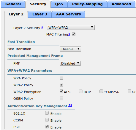
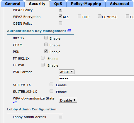
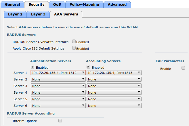
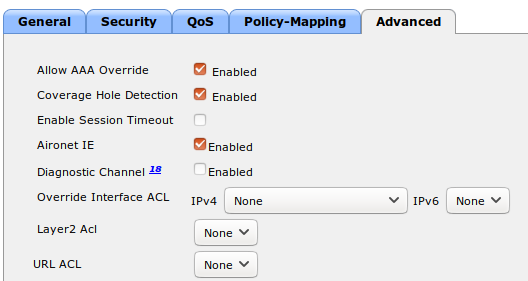
PacketFence Configuration:
- First because there is no way to detect in the RADIUS request that the request is for an SSID configured for IPSK, you need to configure PacketFence to trigger IPSK on a connection profile. To do that, create a new connection profile, set a Filter based on the SSID (Example SSID PSK_SSID), enable IPSK and set a default PSK key. So each time a device will connect on this specific SSID PacketFence will know that it has to answer with specific VSA attributes.
- Second step is to associate the device to a user, you have two ways to do it, the first one is to manually edit an user and in Miscellaneous tab fill the PSK entry (8 characters minimum) then edit a node and change the owner with the one you just edit before. The second way to associate the device is to use a provisioner. There are also 2 ways to do it, use the "IPSK" provisioner (it will show you a page on the portal with the PSK key to use and the SSID to connect to, or use the "Windows/Apple Devices/Android" provisioner and configure it to do IPSK.
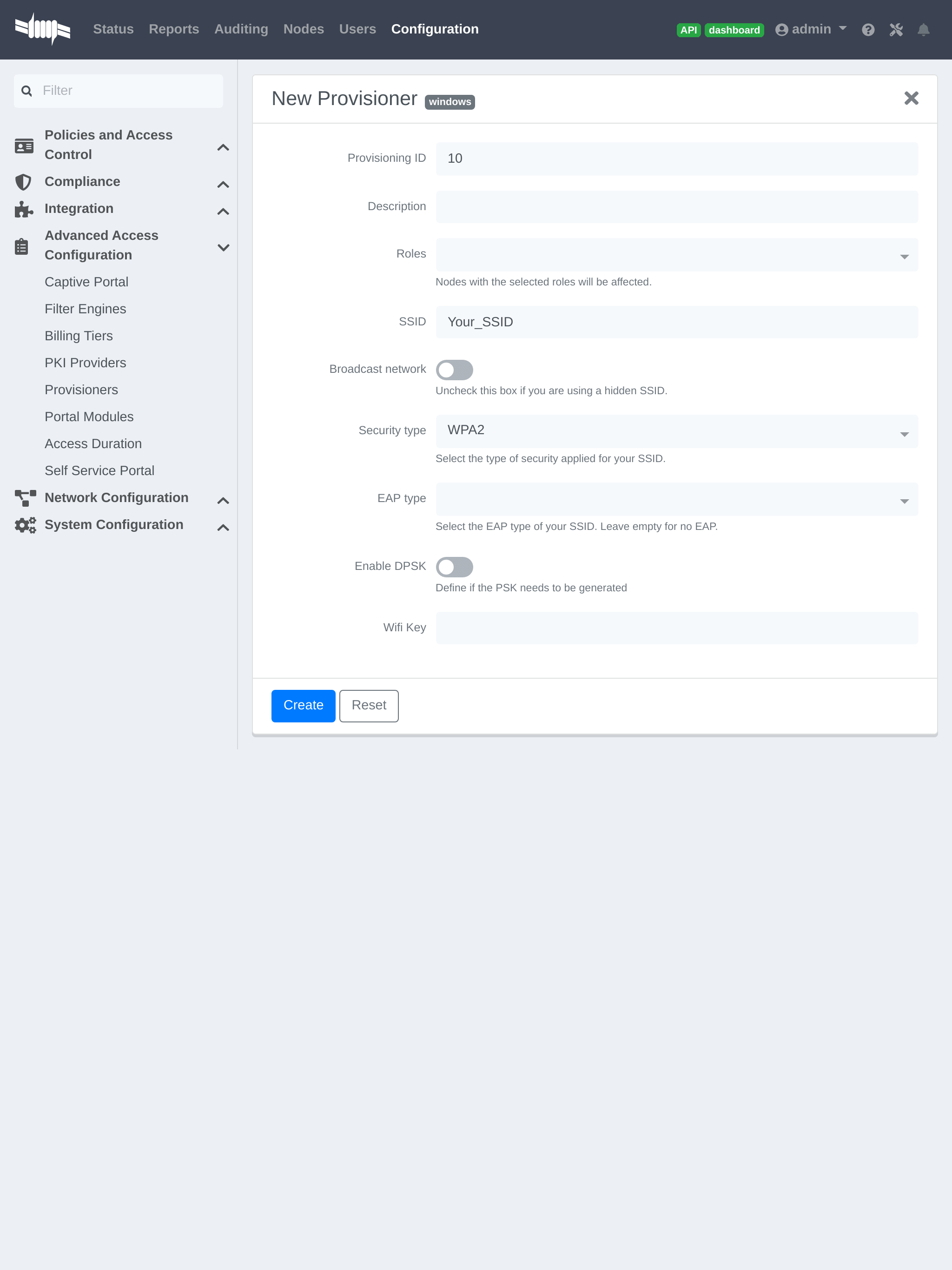
4.11.5. Wireless LAN Controller (IOS XE) 9800
General RADIUS Configuration
Go to Configuration → Security → AAA → Servers / Groups → Servers, click add
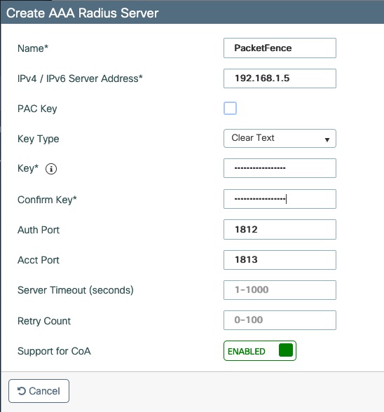
Click Server Groups, click add
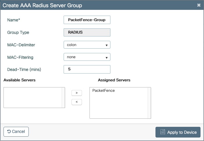
Go to Configuration → Security → AAA → AAA Method List → Authentication, click add
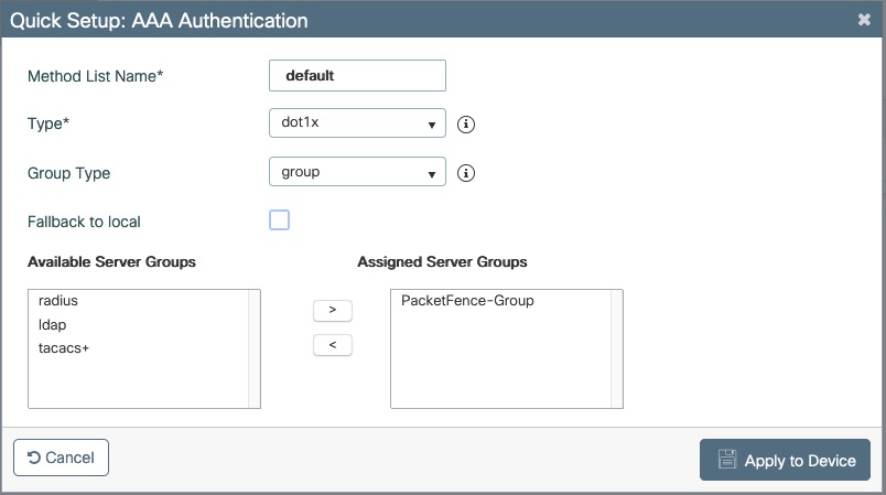
Go to Configuration → Security → AAA → AAA Method List → Authorization, click add
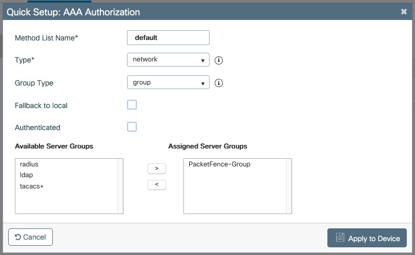
Go to Configuration → Security → AAA → AAA Method List → Accounting, click add
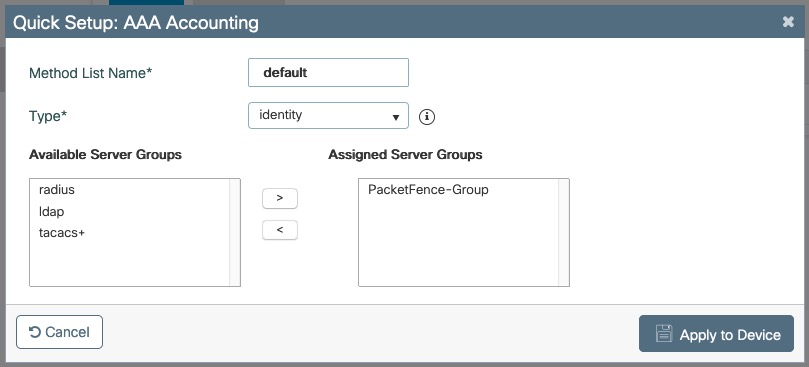
Create WLANs
PF-Open SSID
Go to Configuration → Tags & Profiles → WLANs, click add
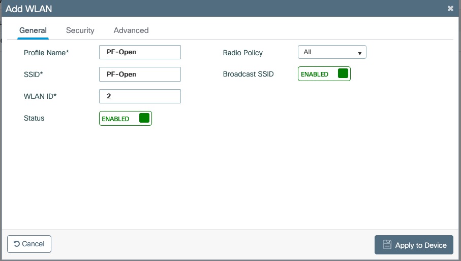
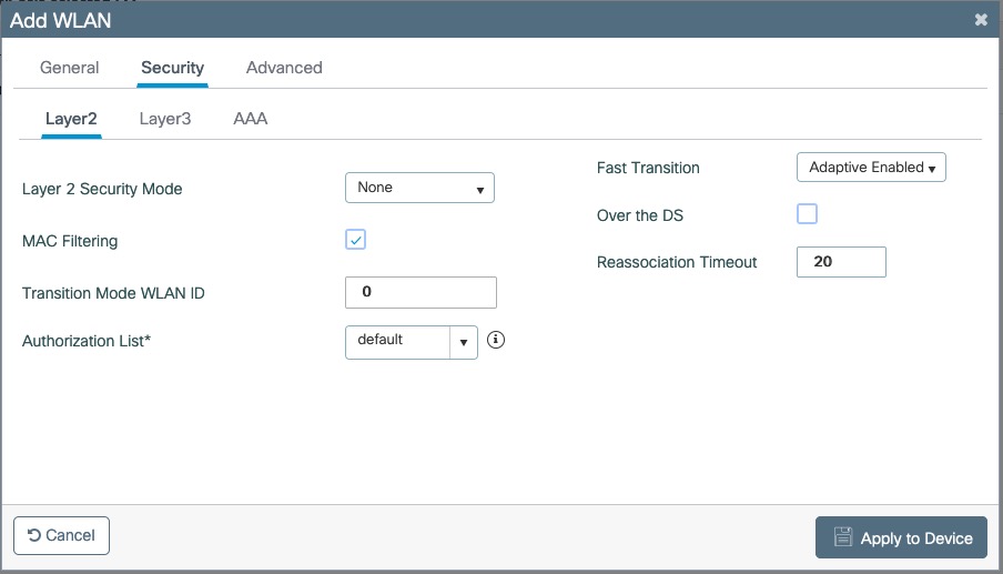
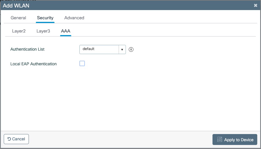
Create Policy Profiles PF-Open
Go to Configuration → Tags & Profiles → Policy, click add
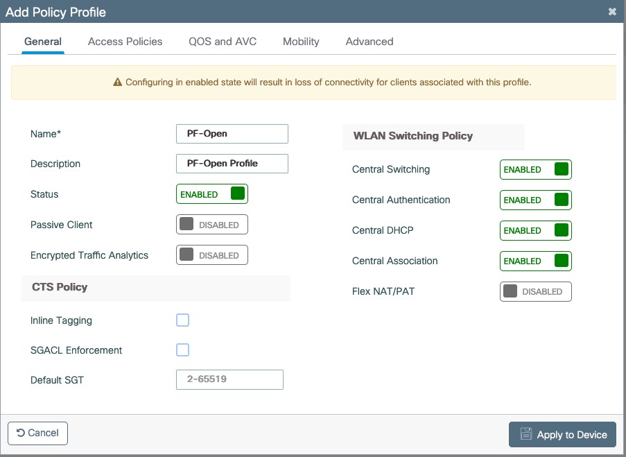
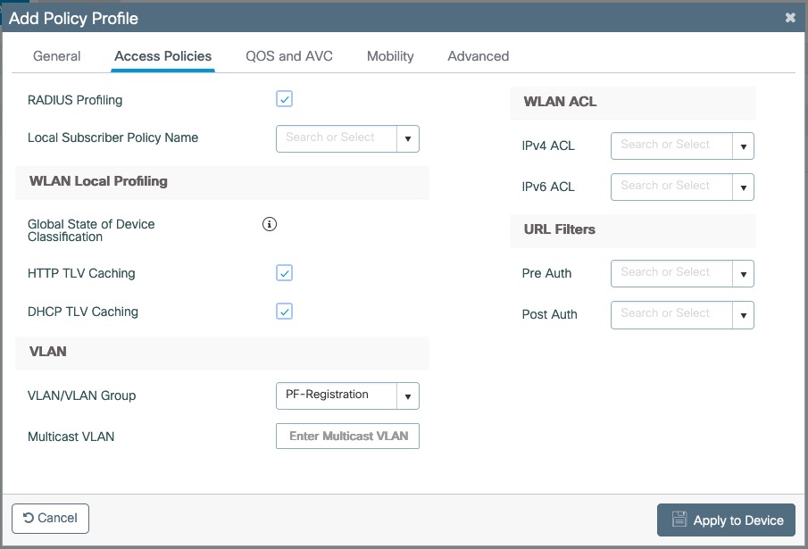
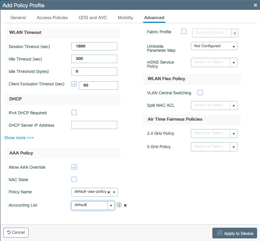
Go to Configuration → Tags & Profiles → Tags, under Policy click add
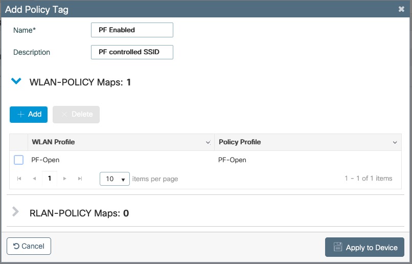
Go to Configuration → Wireless → Access Points
Click on the AP Name or MAC address
Under General → Tags, Select 'PF Enabled'
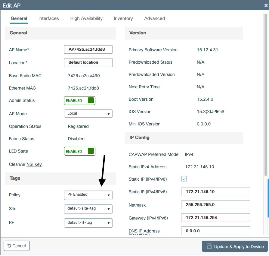
PF-Secure SSID
Go to Configuration → Tags & Profiles → WLANs, click add

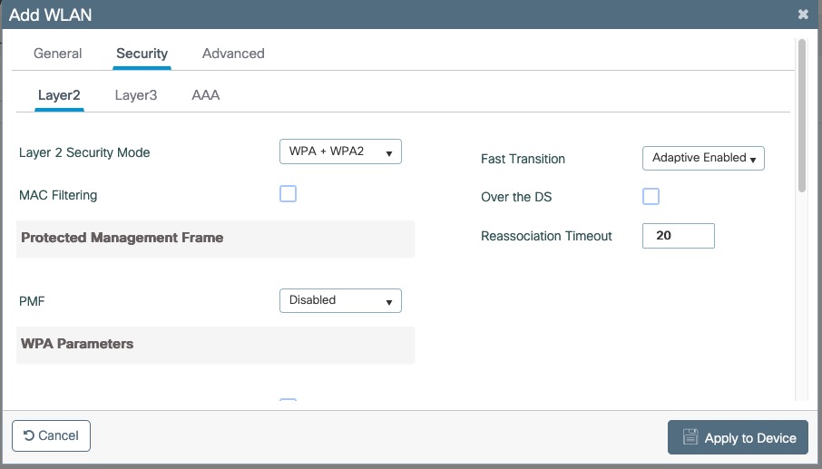
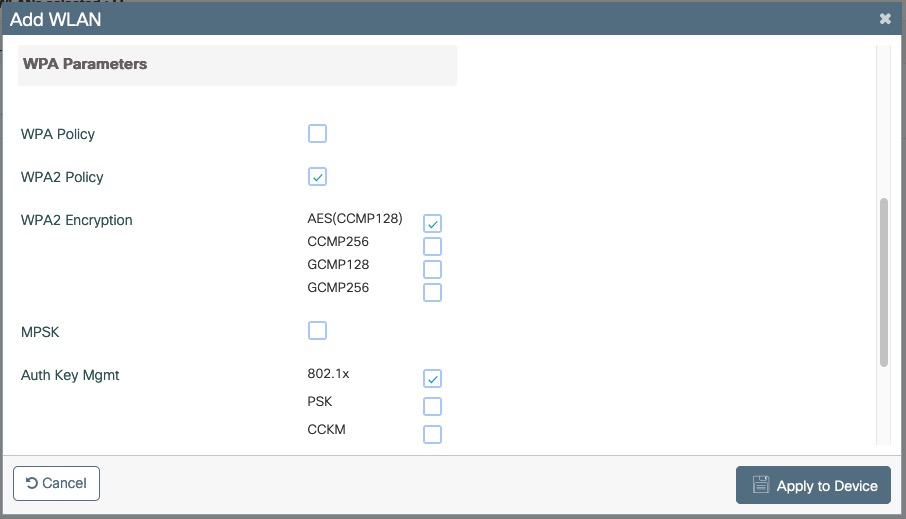

Create Policy Profiles PF-Secure
Go to Configuration → Tags & Profiles → Policy, click add
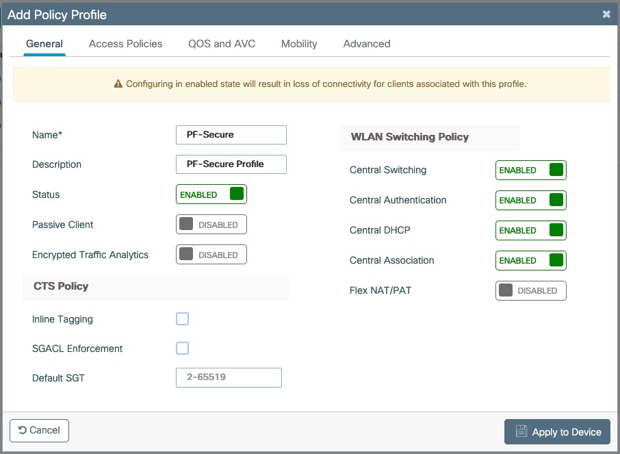
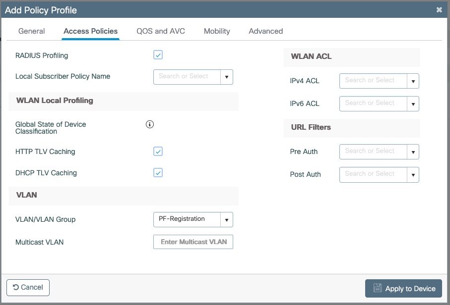

Go to Configuration → Tags & Profiles → Tags, under Policy click add
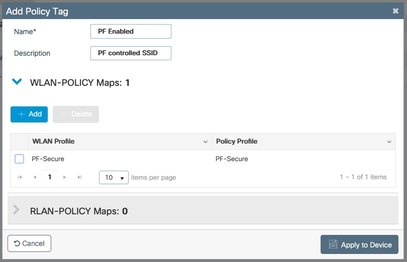
Go to Configuration → Wireless → Access Points
Click on the AP Name or MAC address
Under General → Tags, Select 'PF Enabled'
PF-WebAuth SSID
Create Redirect ACL for Guest Web authentication:
Go to Configuration → Security → ACL, click add
Use ACL Name: Pre-Auth-For-WebRedirectFor ACL Type, select IPv4 Extended
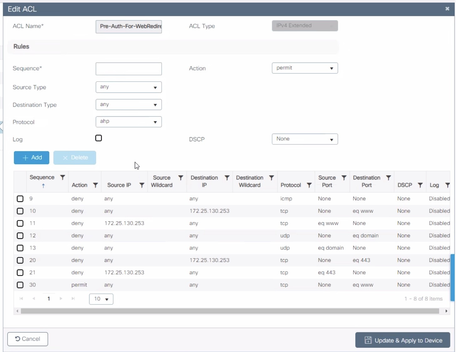
Go to Configuration → Security → ACL, click add
Use ACL Name: Authorize_anyFor ACL Type, select IPv4 Extended
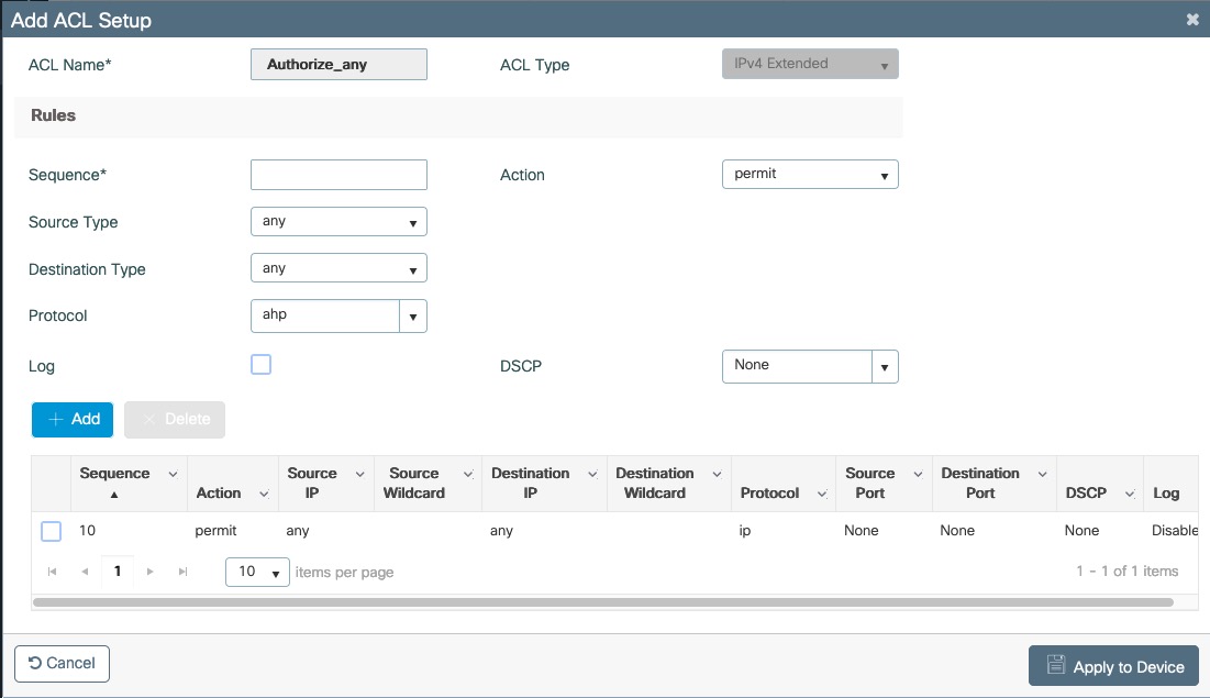
For FlexConnect you will need to enable Central Web Auth
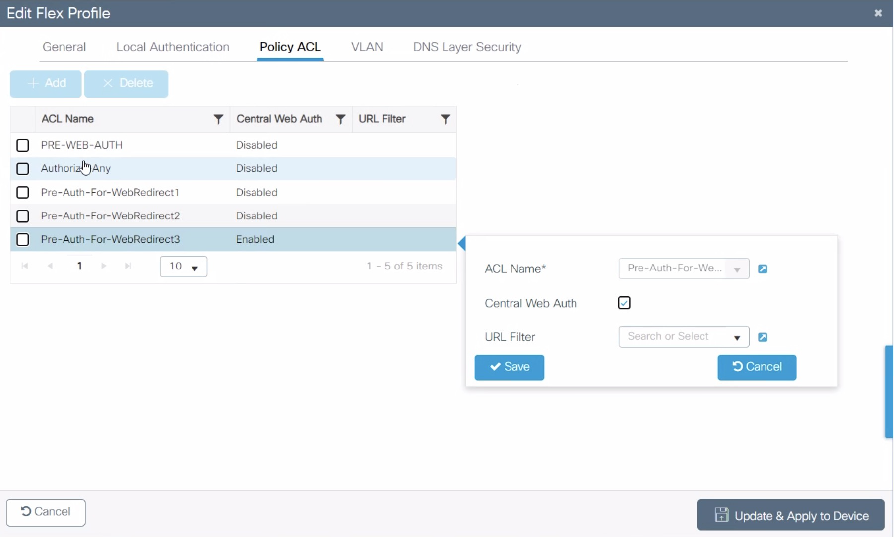
Go to Configuration → Security → Web Auth
Select Type Webauth and enable Web Auth Intercept HTTPs
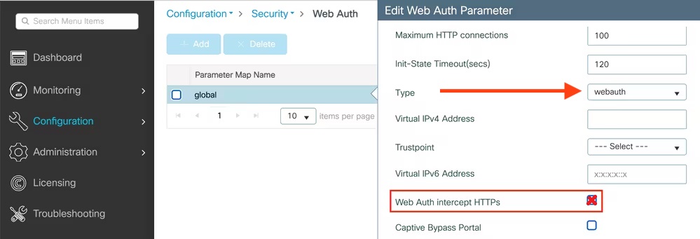
PF-WebAuth SSID creation
Go to Configuration → Tags & Profiles → WLANs, click add

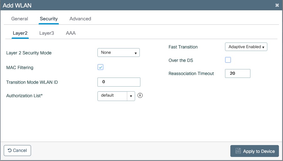

Create Policy Profiles PF-WebAuth
Go to Configuration → Tags & Profiles → Policy, click add
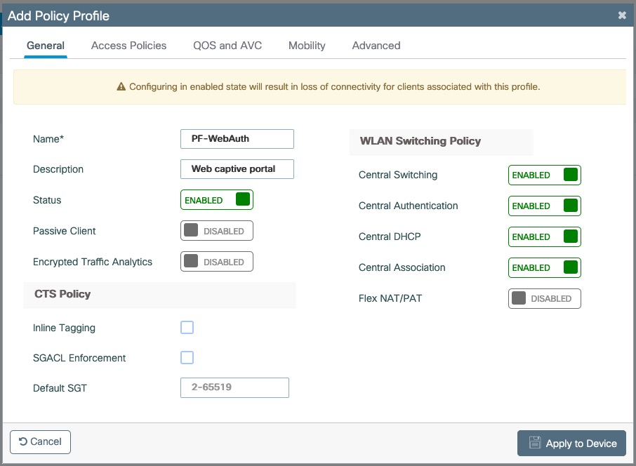
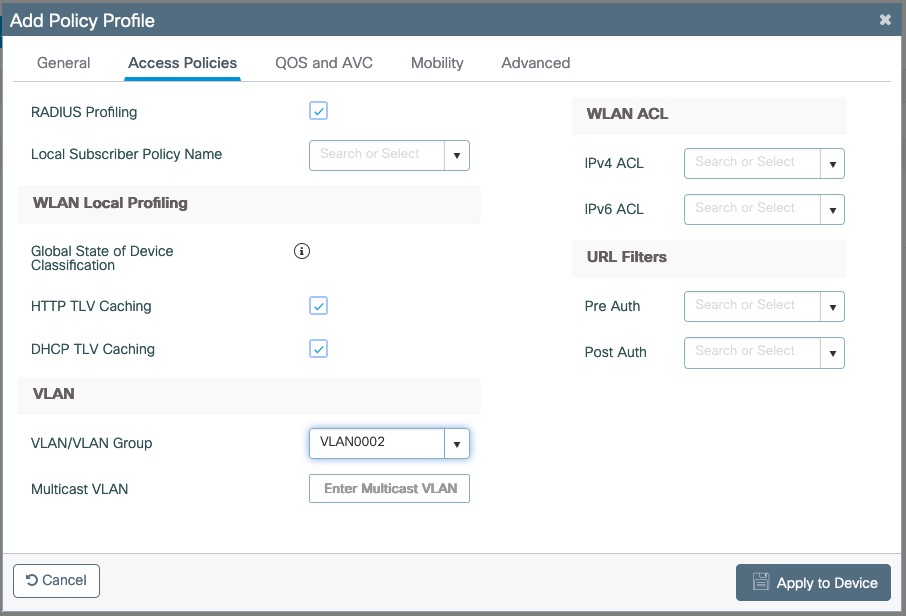
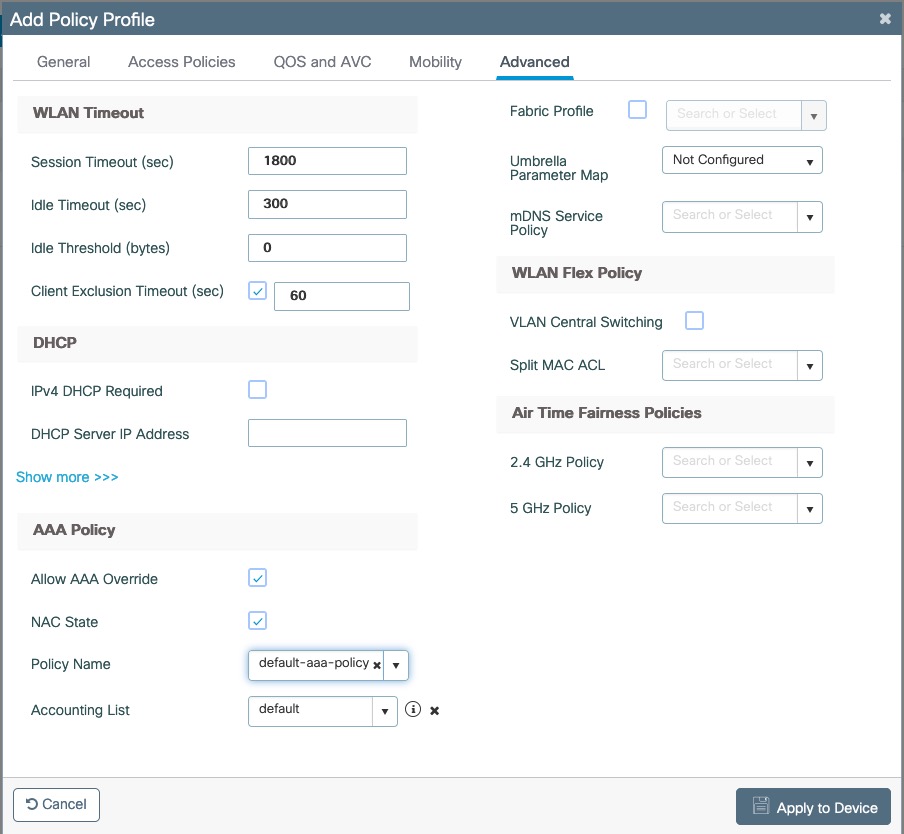
Go to Configuration → Tags & Profiles → Tags, under Policy click add
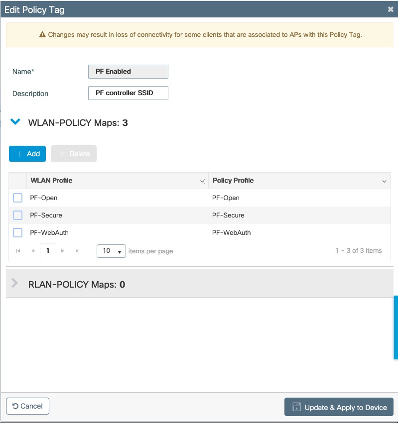
Go to Configuration → Wireless → Access Points
Click on the AP Name or MAC address
Under General → Tags, Select 'PF Enabled'
PacketFence switch configuration
Now you will to create a new switch in PacketFence
Go to Configuration → Policies and Access Control → Switches → New Switch → default
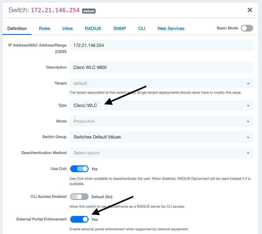
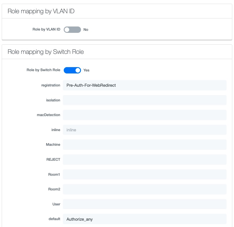
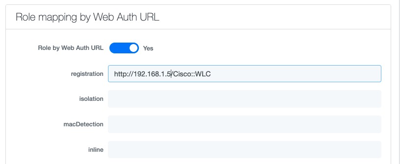
PF-Easy-PSK SSID
Go to Configuration → Tags & Profiles → WLANs, click add
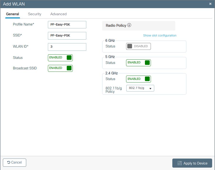
In security Layer2 tab select MAC Filtering, select in AUthorization List the radius server created above. In Auth Key Mgmt (AKM) section select PSK and Easy-PSK.
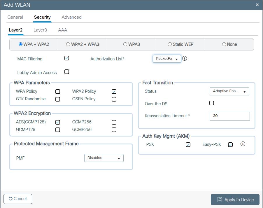
4.11.6. Troubleshooting ignored RADIUS replies
In the event the WLC ignores the RADIUS replies from PacketFence (you receive multiple requests but access is never granted), validate the following elements :
- RADIUS secret is properly configured in PacketFence and the WLC controller.
- The SSL certificate used by PacketFence is not expired.
4.11.7. Device Sensor
When using a Cisco WLC, you can enable device sensor by making sure the configuration looks like the following screenshot:
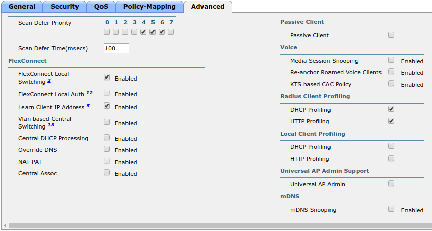
4.12. CoovaChilli
This section has been created in order to help setting up a consumer grade access point running CoovaChilli integration with PacketFence to use UAM capabilities along with PacketFence feature set.
4.12.1. Assumptions
- You have a CoovaChilli capable access point running LEDE/OpenWRT, on which CoovaChilli is installed (CoovaChilli installation is not covered in this guide);
- A working PacketFence server, a CoovaChilli capable access point, and Internet is functional;
- A PacketFence WebAuth enforcement setup will be deployed;
4.12.2. Access Point and CoovaChilli Configuration
We go ahead and start by configuring the access point and CoovaChilli running on it.
These instructions assume that CoovaChilli is installed on the access point. If it’s not, we suggest you search relevant information on the Internet to install CoovaChilli as there are too many network equipment vendors that support CoovaChilli to accurately document this step here.
These instructions also assume that you have an SSID configured on the access point. Assumption is also made that the network interface / bridge is configured and assigned for the given SSID.
You should also make sure to have a default route properly configured on the access point (so that it can access the Internet) and that DNS resolution is working.
Also note that changes on the OpenWRT access point are done using SSH shell access.
Please note that any interface name reference might be different from one equipment vendor to another.
Configure chilli
chilli configuration might differ from one equipment vendor to another one. Just make sure to follow these configuration guidelines and you should be all-set.
-
chilli configuration file can be found under
/etc/config/chilli
-
Edit the following parameters to integrate with PacketFence
option disabled 1 This should be commented out so that chilli is marked asenabledoption dns1 Set this to a working DNS server (this will be used by hotspotclients)option dns2 Set this to a working DNS server (this will be used by hotspotclients)option ipup /etc/chilli/up.sh (Depending on the package, the script pathmight need to be adjusted)option ipdown /etc/chilli/down.sh (Depending on the package, the script pathmight need to be adjusted)option radiusserver1 PacketFence management IPoption radiusserver2 PacketFence management IPoption radiussecret The RADIUS secret that will be used between chilli andPacketFenceoption radiusnasid Access-point IP addressoption dhcpif The network interface / bridge assigned to the SSID (Hotspotclients network)option uamserver http://PACKETFENCE_MANAGEMENT_IP/CoovaChillioption ssid SSID nameoption nasip Access-point IP addressoption coaport 3799
A startup script might be required depending on the equipment vendor. Again, a quick documentation search on the Internet might be the best solution to find the best one
Once set up, you might want to activate chilli at boot (by using the startup script) and finally, reboot the AP.
4.12.3. PacketFence Configuration for CoovaChilli Integration
Having a working PacketFence installation and a configured LEDE / OpenWRT access point running CoovaChilli, the last step is PacketFence configuration for CoovaChilli integration.
To do so, login to the PacketFence admin interface if not already done.
Switch configuration
Click on the 'Configuration' tab and select the 'Switches' menu option under the 'NETWORK' section on the left hand side.
On the bottom of the page, click the 'Add switch to group' button then select the 'default' to bring up the 'New Switch' configuration modal window.
'Definition' tab
- IP: Access-point IP address
- Type: CoovaChilli
- Mode: Production
- External Portal Enforcement: Checked
'RADIUS' tab
- Secret Passphrase: The RADIUS secret configured in the previous step
Click 'Save'
Portal configuration
It is required to disable HTTPS redirection by clicking the 'Configuration' tab and then the 'Captive portal' menu option on the left hand side. Make sure 'Secure redirect' is unchecked.
4.13. D-Link
4.13.1. DWL Access-Points and DWS 3026
4.14. Extreme Networks
4.14.1. Access points AP305C (managed by Extreme Cloud IQ Controller)
In such deployment, PacketFence communicates directly with the access points using RADIUS. The Extreme Cloud IQ controller is only used to configure access points in a central place.
Web authentication
Extreme Cloud IQ Controller
On the Extreme Cloud IQ Controller, there should already be two built-in IP Firewall policies:
- Redirect-only policy: this policy must have "redirect" rules
- Internet-access-only policy
On the Extreme Cloud IQ Controller, create two user profiles:
-
Registration
- VLAN: 5
- Firewall rules: Enabled
- IP Firewall Name: Redirect-only policy
- Redirect URL: http://192.168.1.5/Extreme::AP
-
Guest
- VLAN: 5
- Firewall rules: Enabled
- IP Firewall Name: Internet-access-only policy
Still, on the Extreme Cloud IQ Controller, create a wireless network with the following configuration:
-
SSID Authentication: Open
- Enable Captive Web Portal: No
-
MAC Authentication tab
- Enable MAC authentication: Yes
- Authentication protocol: CHAP
-
Authenticate via RADIUS server
-
Create a RADIUS group with an External RADIUS Server
- Permit Dynamic Change Of Authorization Messages (RFC 3576): Enabled
-
Create a RADIUS group with an External RADIUS Server
-
User access settings
-
Apply a different user profile to various clients and user groups: Enabled
-
Allow user profile assignment using RADIUS attributes in addition to the
three tunnel RADIUS attributes: Enabled
- Standard RADIUS Attribute: Filter-Id
-
Allow user profile assignment using RADIUS attributes in addition to the
three tunnel RADIUS attributes: Enabled
-
Apply a different user profile to various clients and user groups: Enabled
Under User access settings, you need to create following rules:
| User profile name | VLAN/VLAN Group | Assignment rules |
|---|---|---|
Registration |
5 |
If Filter-ID equals "Registration" |
Guest |
5 |
If Filter-ID equals "Guest" |
PacketFence
Create a switch with following configuration:
-
Definition tab
- Identifier: subnet of your Extreme AP
- External portal enforcement: Yes
- Deauthentication method: RADIUS
-
Roles tab
-
Role by Switch Role: Yes
- registration: Registration
- guest: Guest
-
Role by Switch Role: Yes
4.15. Extricom
4.15.1. EXSW Wireless Switches (Controllers)
In order to have the Extricom controller working with PacketFence, you need to define two ESSID definition, one for the "public" network, and one for the "secure" network. This can be done under a very short time period since Extricom supports RADIUS assigned VLANs out of the box.
You first need to configure you RADIUS server. This is done under the: WLAN Settings → RADIUS tab. Enter the PacketFence RADIUS server information. For the ESSID configuration. in the administration UI, go to WLAN Settings → ESSID definitions. Create the profiles per the following:
Public SSID
- MAC Authentication must be ticked
- Encryption method needs to be set to None
- Select PacketFence as the MAC Authentication RADIUS server (previously added)
Secure SSID
- Encryption method needs to be set to WPA Enterprise/WPA2 Enterprise
- AES only needs to be selected
- Select PacketFence as the RADIUS server (previously added)
The final step is to enable SNMP Agent and SNMP Traps on the controller. This is done under the following tab in the administrative UI: Advanced → SNMP.
4.16. Fortinet FortiGate
This section shows how to configure a 802.1X SSID on a Fortigate 50E running on FortiOS 5.4.
You will need to have the CLI access on the Fortigate to do the configuration.
4.16.1. RADIUS
FGT50E # config user radiusFGT50E (radius) # edit packetfencenew entry 'packetfence' addedFGT50E (packetfence) # set server 192.168.1.5FGT50E (packetfence) # set secret useStrongerSecretFGT50E (packetfence) # set nas-ip 192.168.1.1FGT50E (packetfence) # set radius-coa enableFGT50E (packetfence) # config accounting-serverFGT50E (accounting-server) # edit 1new entry '1' addedFGT50E (1) # set status enableFGT50E (1) # set server 192.168.1.5FGT50E (1) # set secret useStrongerSecretFGT50E (1) # endFGT50E (packetfence) # end
4.16.2. 802.1X SSID
FGT50E #config wireless-controller vapFGT50E (vap) # edit PF-Securenew entry 'PF-Secure' addedFGT50E (PF-Secure) # edit "PF-Secure"FGT50E (PF-Secure) # set vdom "root"FGT50E (PF-Secure) # set ssid "PF-Secure"FGT50E (PF-Secure) # set security wpa2-only-enterpriseFGT50E (PF-Secure) # set auth radiusFGT50E (PF-Secure) # set radius-server "packetfence"FGT50E (PF-Secure) # set schedule "always"FGT50E (PF-Secure) # set local-bridging enableFGT50E (PF-Secure) # set dynamic-vlan enableFGT50E (PF-Secure) # end
4.17. Hostapd
4.17.1. Introduction
This section will provide an example for the configuration of an open SSID (not encrypted) and a secure SSID (802.1X). You will need to install wpad and hostapd. These two SSIDs will do RADIUS authentication against PacketFence. You can not have both SSID configured on the same access point at the same time, there is a limitation with the DAE server.
4.17.2. Assumptions
- You have a configured PacketFence environment with working test equipment
- The management IP of PacketFence will be 192.168.1.10 and has s3cr3t as its RADIUS shared secret
- You have an access point with OpenWrt Chaos Calmer 15.05 installed
4.17.3. Quick installation
Packages Installation
You can install the packages from the web interface of OpenWrt.
Go to System → Software
First update the repos by clicking the button Update lists if it’s not up to date.
Then you will have to install the packages of Hostapd and wpad.
Go to the tab Available packages and then search for the package hostapd into
the Filter: field.
Click Install the hostapd-common package, the actual version is 2015-03-25-1.
Do the same process for the wpad package version 2015-03-25-1.
Dynamic VLAN Configuration
Connect using SSH to the AP and create the file : /etc/config/hostapd.vlan
* wlan0.#
Hostapd Configuration
You will need to modify the hostapd script that comes with the package that we previously installed.
Connect using SSH to the AP and run these commands:
cd /lib/netifd/mv hostapd.sh hostapd.sh.oldopkg install curlcurl --insecure https://github.com/inverse-inc/packetfence/tree/devel/addons/hostapd/hostapd-15.05.sh > hostapd.shwifi
Configure the SSIDs
To configure the PF-Open SSID, we will edit the file /etc/config/wireless:
# Definition of the radioconfig wifi-device 'radio0'option type 'mac80211'option channel '11'option hwmode '11g'option path 'pci0000:00/0000:00:00.0'option htmode 'HT20'# Configuration of the Open SSIDoption device 'radio0'option mode 'ap'option vlan_file '/etc/config/hostapd.vlan'option vlan_tagged_interface 'eth0'option vlan_naming '0'option dynamic_vlan '2'option auth_port '1812'option auth_server '192.168.1.10'option auth_secret 's3cr3t'option acct_port '1813'option acct_server '192.168.1.10'option acct_secret 's3cr3t'option dae_port '3799'option dae_client '192.168.1.10'option dae_secret 's3cr3t'option nasid 'Lobby'option encryption 'none'option ssid 'OpenWRT-Open'
Configure the PF-Secure SSID:
# Definition of the radioconfig wifi-device 'radio0'option type 'mac80211'option channel '11'option hwmode '11g'option path 'pci0000:00/0000:00:00.0'option htmode 'HT20'config wifi-ifaceoption device 'radio0'option mode 'ap'option vlan_file '/etc/config/hostapd.vlan'option vlan_tagged_interface 'eth0'option vlan_naming '0'option dynamic_vlan '2'option auth_port '1812'option auth_server '192.168.1.10'option auth_secret 's3cr3t'option acct_port '1813'option acct_server '192.168.1.10'option acct_secret 's3cr3t'option dae_port '3799'option dae_client '192.168.1.10'option dae_secret 's3cr3t'option nasid 'Lobby'option encryption 'wpa2'option ssid 'OpenWRT-Secure'
In order to apply this configuration, when you are connected using SSH on the AP, run the command 'wifi'. It will reload the configuration and broadcast the SSID. If you want to debug, you can use the command 'logread'.
PacketFence Configuration
Log in to the PacketFence administration web page and go under Configuration → Policies and Access Control → Switches → Add switch.
Definition:
- IP Address/MAC Address/Range (CIDR): IP of your access point
- Type: Hostapd
- Mode: production
- Deauthentication Method: RADIUS
- Dynamic Uplinks: Checked
Roles:
- Role by VLAN ID: Checked
- Registration: Your registration VLAN ID
- Isolation: Your isolation VLAN ID
RADIUS:
- Secret Passphrase: s3cr3t
Save this configuration by clicking the Save button.
Troubleshoot
There are few things you can do/check to see if your configuration is working.
To check the wireless configuration: uci show wireless or cat
/etc/config/wireless
To check if your configuration (depend on the equipment) is correctly set into the Hostapd configuration file: cat /var/run/hostapd-phy0.conf
4.18. Huawei
4.18.1. AC6605 Controller
PacketFence supports this controller with the following technologies:
- Wireless 802.1X
- Wireless MAC Authentication
Controller configuration
Setup NTP server:
<AC>system-view[AC] ntp-service unicast-server 208.69.56.110
Setup the radius server (@IP of PacketFence) authentication + accounting:
In this configuration I will use the ip address of the VIP of PacketFence: 192.168.1.2; Registration VLAN : 145, Isolation VLAN : 146
<AC>system-view[AC] radius-server template radius_packetfence[AC-radius-radius_packetfence] radius-server authentication 192.168.1.2 1812weight 80[AC-radius-radius_packetfence] radius-server accounting 192.168.1.2 1813 weight80[AC-radius-radius_packetfence] radius-server shared-key cipher s3cr3t[AC-radius-radius_packetfence] undo radius-server user-name domain-included[AC-radius-radius_packetfence] quit[AC] radius-server authorization 192.168.1.2 shared-key cipher s3cr3tserver-group radius_packetfence[AC] aaa[AC-aaa] authentication-scheme radius_packetfence[AC-aaa-authen-radius_packetfence] authentication-mode radius[AC-aaa-authen-radius_packetfence] quit[AC-aaa] accounting-scheme radius_packetfence[AC-aaa-accounting-radius_packetfence] accounting-mode radius[AC-aaa-accounting-radius_packetfence] quit
[AC-aaa] domain your.domain.com[AC-aaa-domain-your.domain.com] authentication-scheme radius_packetfence[AC-aaa-domain-your.domain.com] accounting-scheme radius_packetfence[AC-aaa-domain-your.domain.com] radius-server radius_packetfence[AC-aaa-domain-your.domain.com] quit[AC-aaa] quit
Create an Secure dot1x SSID
Activate the dotx globally:
<AC>system-view[AC] dot1x enable
Create your secure dot1x ssid:
Configure WLAN-ESS 0 interfaces:
[AC] interface Wlan-Ess 0[AC-Wlan-Ess0] port hybrid untagged vlan 145 to 146[AC-Wlan-Ess0] dot1x enable[AC-Wlan-Ess0] dot1x authentication-method eap[AC-Wlan-Ess0] permit-domain name your.domain.com[AC-Wlan-Ess0] force-domain name your.domain.com[AC-Wlan-Ess0] default-domain your.domain.com[AC-Wlan-Ess0] quit
Configure AP parameters:
Configure radios for APs:
[AC] wlan[AC-wlan-view] wmm-profile name huawei-ap[AC-wlan-wmm-prof-huawei-ap] quit[AC-wlan-view] radio-profile name huawei-ap[AC-wlan-radio-prof-huawei-ap] radio-type 80211gn[AC-wlan-radio-prof-huawei-ap] wmm-profile name huawei-ap[AC-wlan-radio-prof-huawei-ap] quit[AC-wlan-view] ap 1 radio 0[AC-wlan-radio-1/0] radio-profile name huawei-apWarning: Modify the Radio type may cause some parameters of Radio resume default value, are you sure to continue?[Y/N]: y[AC-wlan-radio-1/0] quit
Configure a security profile named huawei-ap. Set the security policy to WPA authentication, authentication method to 802.1X+PEAP, and encryption mode to CCMP:
[AC-wlan-view] security-profile name huawei-ap-wpa2[AC-wlan-sec-prof-huawei-ap-wpa2] security-policy wpa2[AC-wlan-sec-prof-huawei-ap-wpa2] wpa-wpa2 authentication-method dot1xencryption-method ccmp[AC-wlan-sec-prof-huawei-ap-wpa2] quit
Configure a traffic profile:
[AC-wlan-view] traffic-profile name huawei-ap[AC-wlan-wmm-traffic-huawei-ap] quit
Configure service sets for APs, and set the data forwarding mode to direct forwarding:
The direct forwarding mode is used by default.
[AC-wlan-view] service-set name PacketFence-dot1x[AC-wlan-service-set-PacketFence-dot1x] ssid PacketFence-Secure[AC-wlan-service-set-PacketFence-dot1x] wlan-ess 0[AC-wlan-service-set-PacketFence-dot1x] service-vlan 1[AC-wlan-service-set-PacketFence-dot1x] security-profile name huawei-ap-wpa2[AC-wlan-service-set-PacketFence-dot1x] traffic-profile name huawei-ap[AC-wlan-service-set-PacketFence-dot1x] forward-mode tunnel[AC-wlan-service-set-PacketFence-dot1x] quit
Configure VAPs and deliver configurations to the APs:
[AC-wlan-view] ap 1 radio 0[AC-wlan-radio-1/0] service-set name PacketFence-dot1x[AC-wlan-radio-1/0] quit[AC-wlan-view] commit ap 1
Create your Open ssid
Activate the mac-auth globally:
<AC>system-view[AC] mac-authen[AC] mac-authen username macaddress format with-hyphen[AC] mac-authen domain your.domain.com
Create your Open ssid:
Configure WLAN-ESS 1 interfaces:
[AC] interface Wlan-Ess 1[AC-Wlan-Ess1] port hybrid untagged vlan 145 to 146[AC-Wlan-Ess1] mac-authen[AC-Wlan-Ess1] mac-authen username macaddress format without-hyphen[AC-Wlan-Ess1] permit-domain name your.domain.com[AC-Wlan-Ess1] force-domain name your.domain.com[AC-Wlan-Ess1] default-domain your.domain.com[AC-Wlan-Ess1] quit
Configure AP parameters:
Configure a security profile named huawei-ap-wep. Set the security policy to WEP authentication.
[AC]wlan[AC-wlan-view] security-profile name huawei-ap-wep[AC-wlan-sec-prof-huawei-ap-wep] security-policy wep[AC-wlan-sec-prof-huawei-ap-wep] quit
Configure service sets for APs, and set the data forwarding mode to direct forwarding:
The direct forwarding mode is used by default.
[AC-wlan-view] service-set name PacketFence-WEP[AC-wlan-service-set-PacketFence-WEP] ssid PacketFence-Open[AC-wlan-service-set-PacketFence-WEP] wlan-ess 1[AC-wlan-service-set-PacketFence-WEP] service-vlan 1[AC-wlan-service-set-PacketFence-WEP] security-profile name huawei-ap-wep[AC-wlan-service-set-PacketFence-WEP] traffic-profile name huawei-ap (alreadycreated before)[AC-wlan-service-set-PacketFence-WEP] forward-mode tunnel[AC-wlan-service-set-PacketFence-WEP] quit
Configure VAPs and deliver configurations to the APs:
[AC-wlan-view] ap 1 radio 0[AC-wlan-radio-1/0] service-set name PacketFence-WEP[AC-wlan-radio-1/0] quit[AC-wlan-view] commit ap 1
4.19. Meraki
To add the AP on PacketFence use the internal IP of the AP.
The 'Disconnect port' field must be set to '1700'.
4.19.1. WebAuth
Configure Meraki controller for Web authentication.
Configure your SSID as shown below:
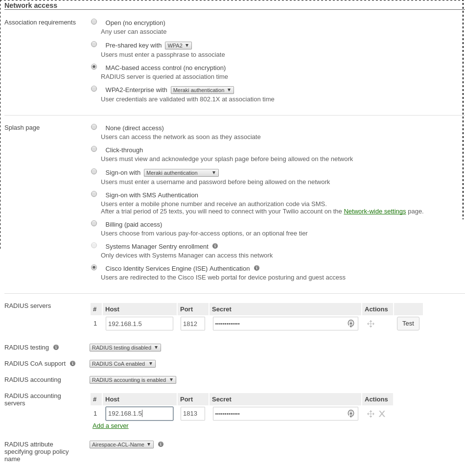
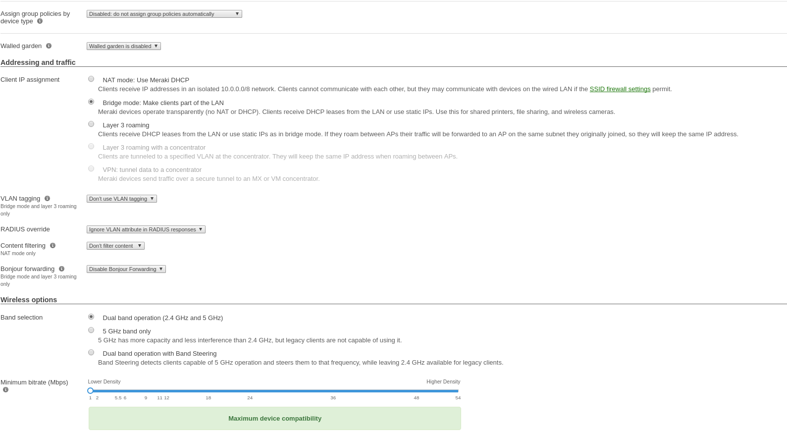
Use switch module "Meraki cloud controller V2" for this configuration.
Configure device roles for your network. Go to 'Network-wide→Group policies' to
create policies configurable as roles in PacketFence switch configuration.
Creating policy Guest:
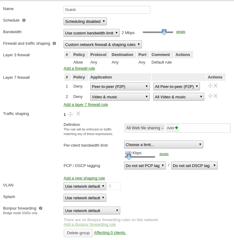
Your configuration for the tab "Roles" in PacketFence will look like the following:
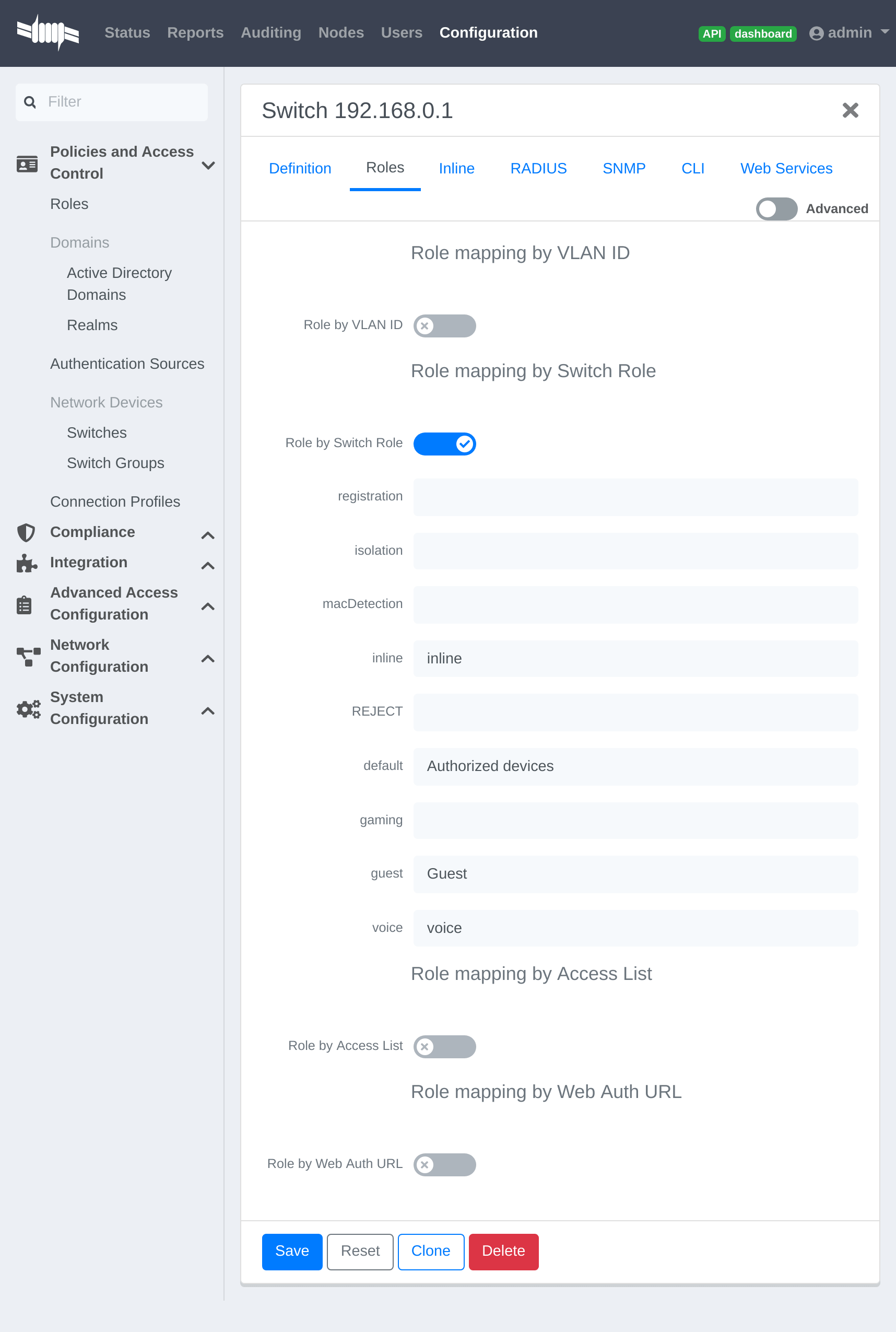
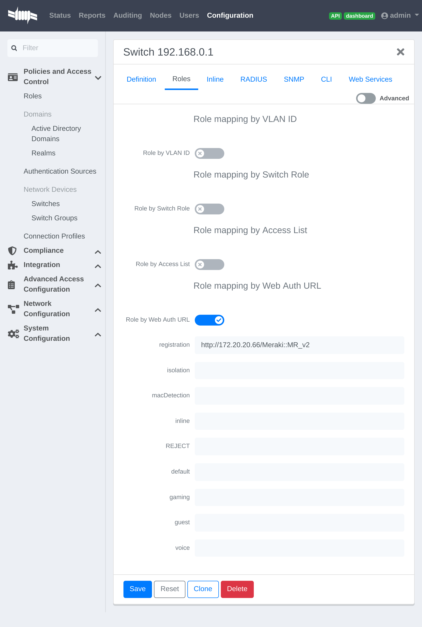
URL in registration field should be in the form: 'http://<your_captive_portal_ip>/Meraki::MR_v2'
4.19.2. VLAN enforcement
This section will cover how to configure the Meraki WiFI controller to use with
VLAN enforcement, use the configuration in the section WebAuth for the SSID.
In the configuration of PacketFence, use "Role by VLAN ID" and fill your VLANs matching roles.
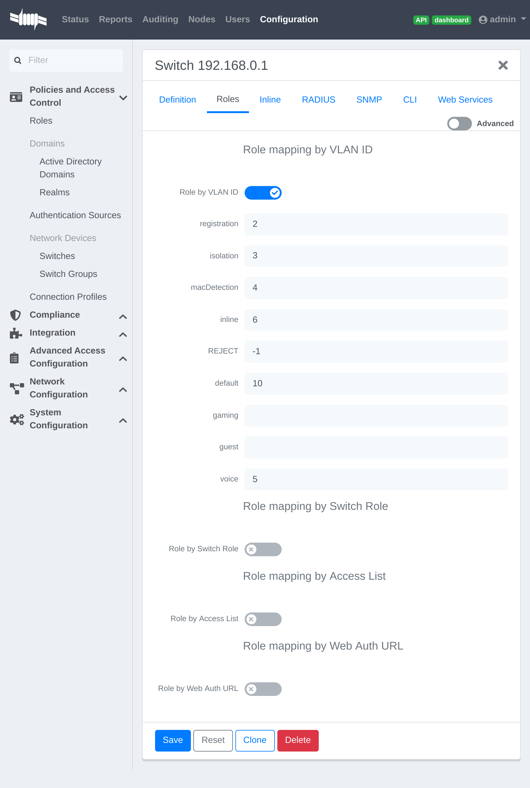
4.19.3. Dynamic PSK (Pre-Shared Key)
This section will cover how to configure the Meraki WiFI controller to use with Dynamic PSK with PacketFence.
You will be able to attribute one PSK per user to use on every device they want. There is a common key to connect to a given PSK secured SSID to register and you will have an option to provision your device with that configuration on Windows, Apple and Android devices.
Create the SSID
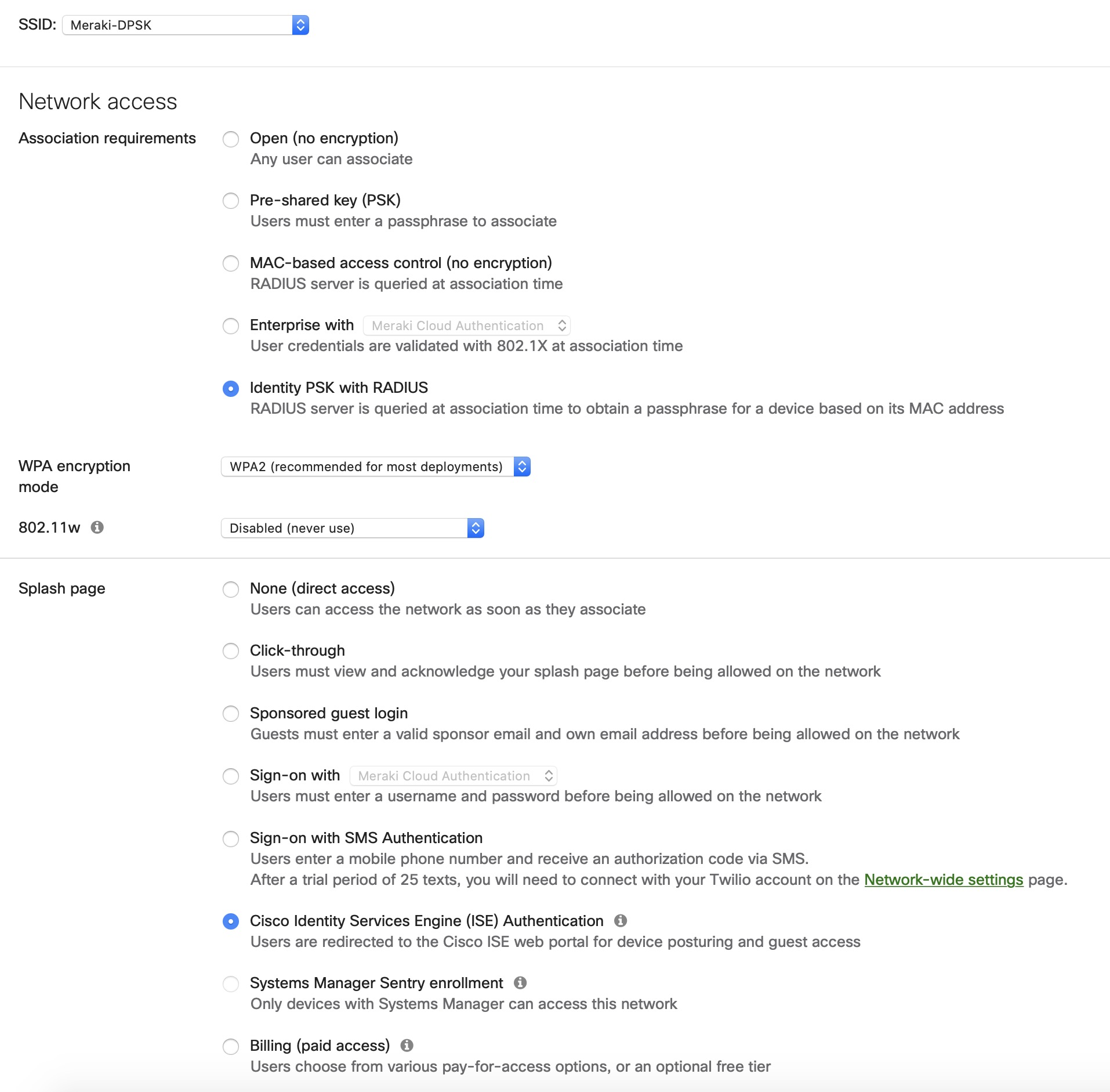
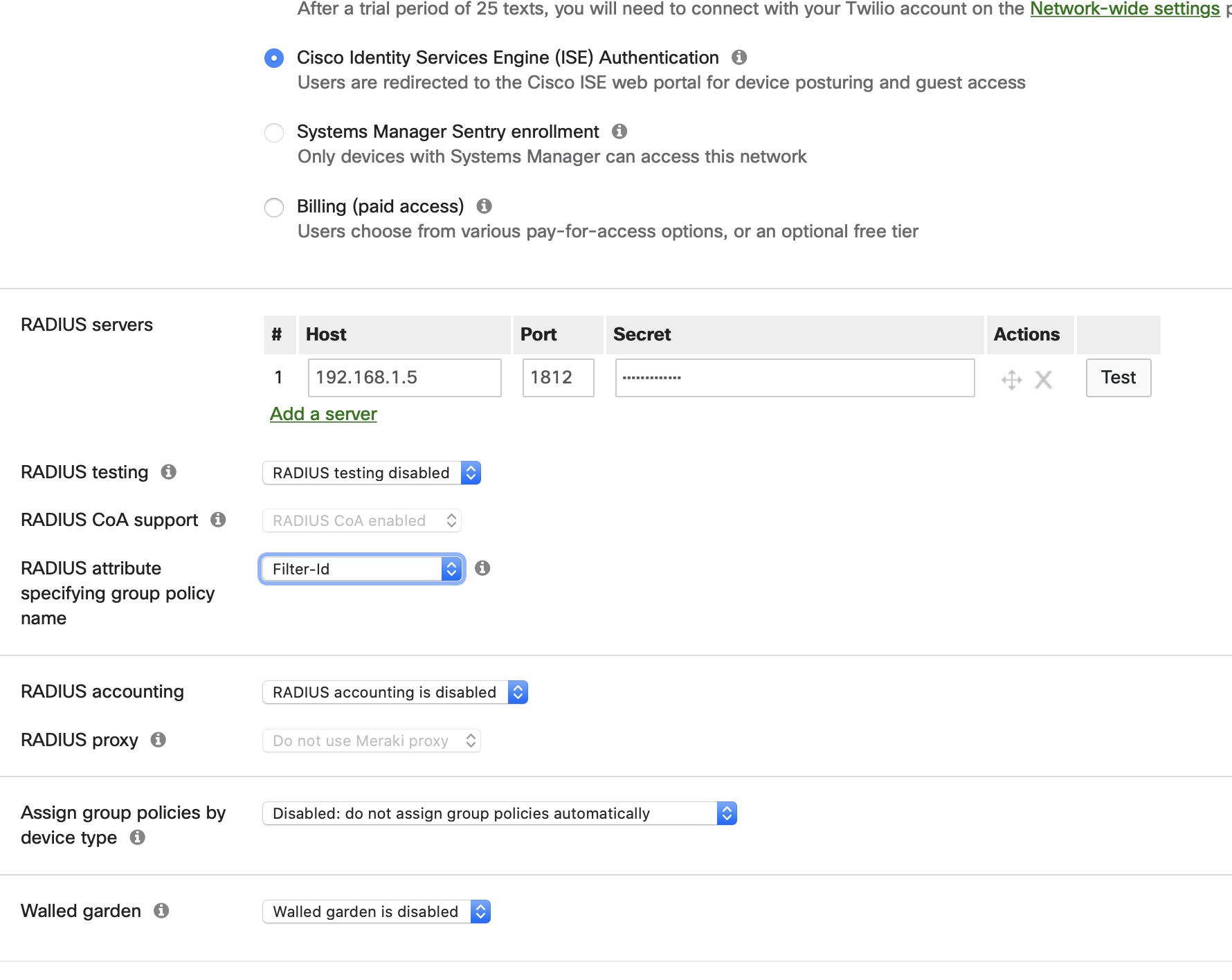
Provioner configuration
Go to Configuration > Advanced Access Configuration > Provisioner > New provisioner > DPSK
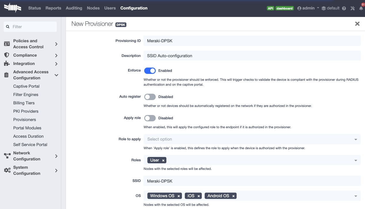
Connection profile configuration
Go to Configuration > Policies and Access Control > Connection Profiles > New Connection Profile
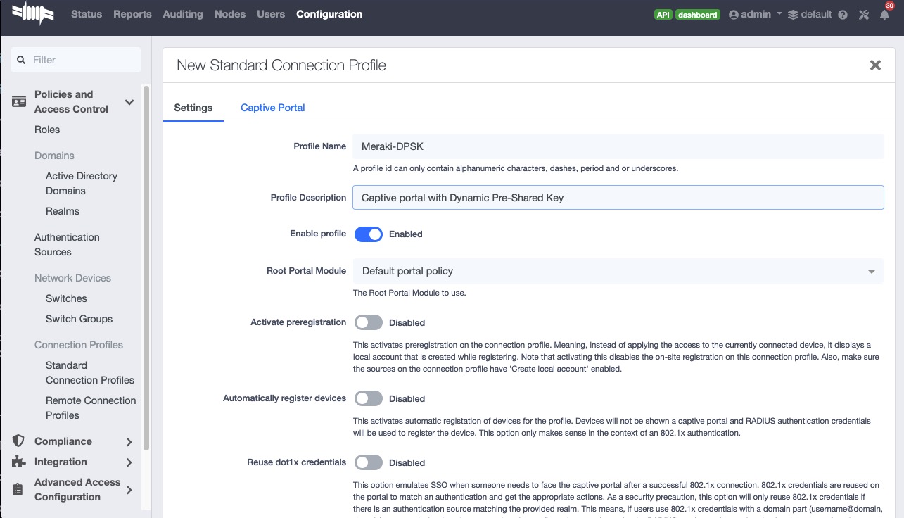
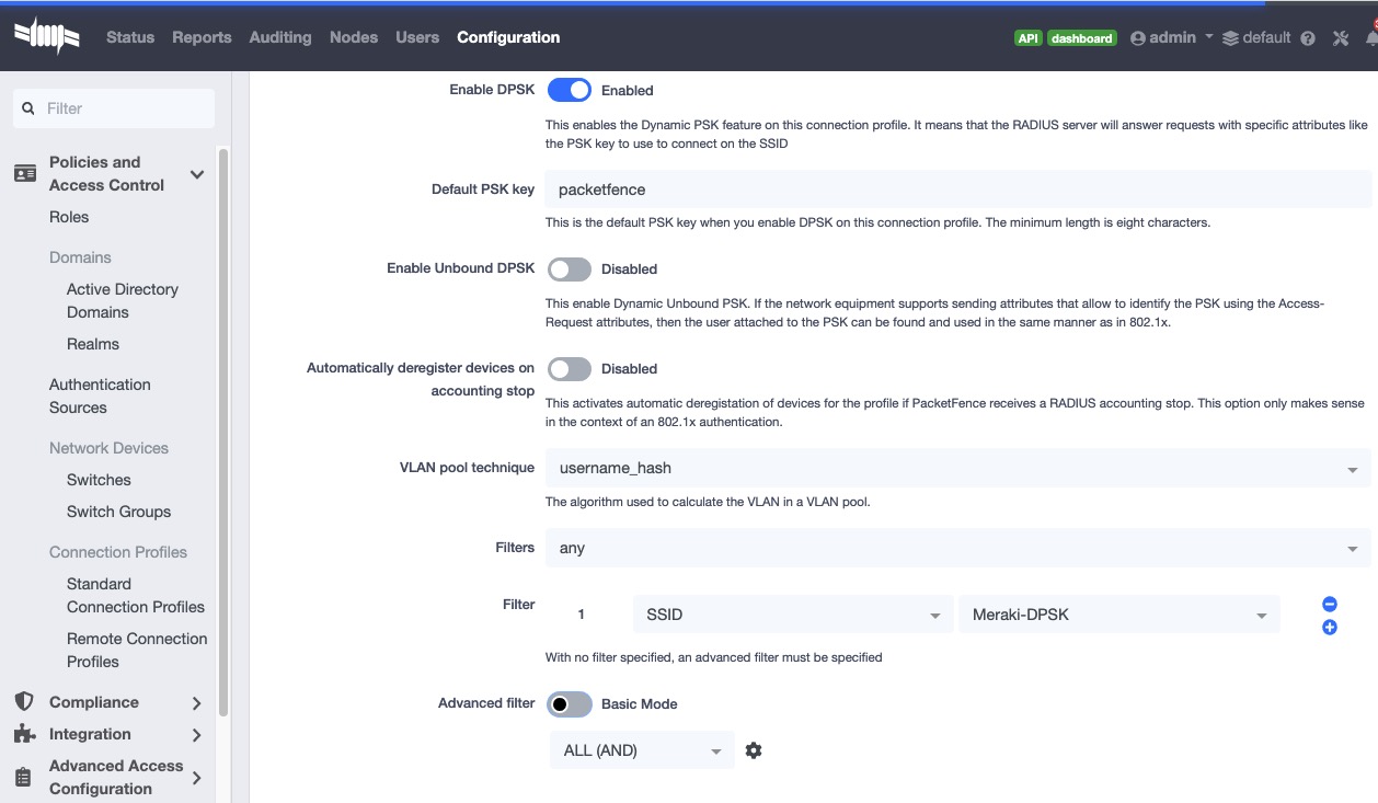
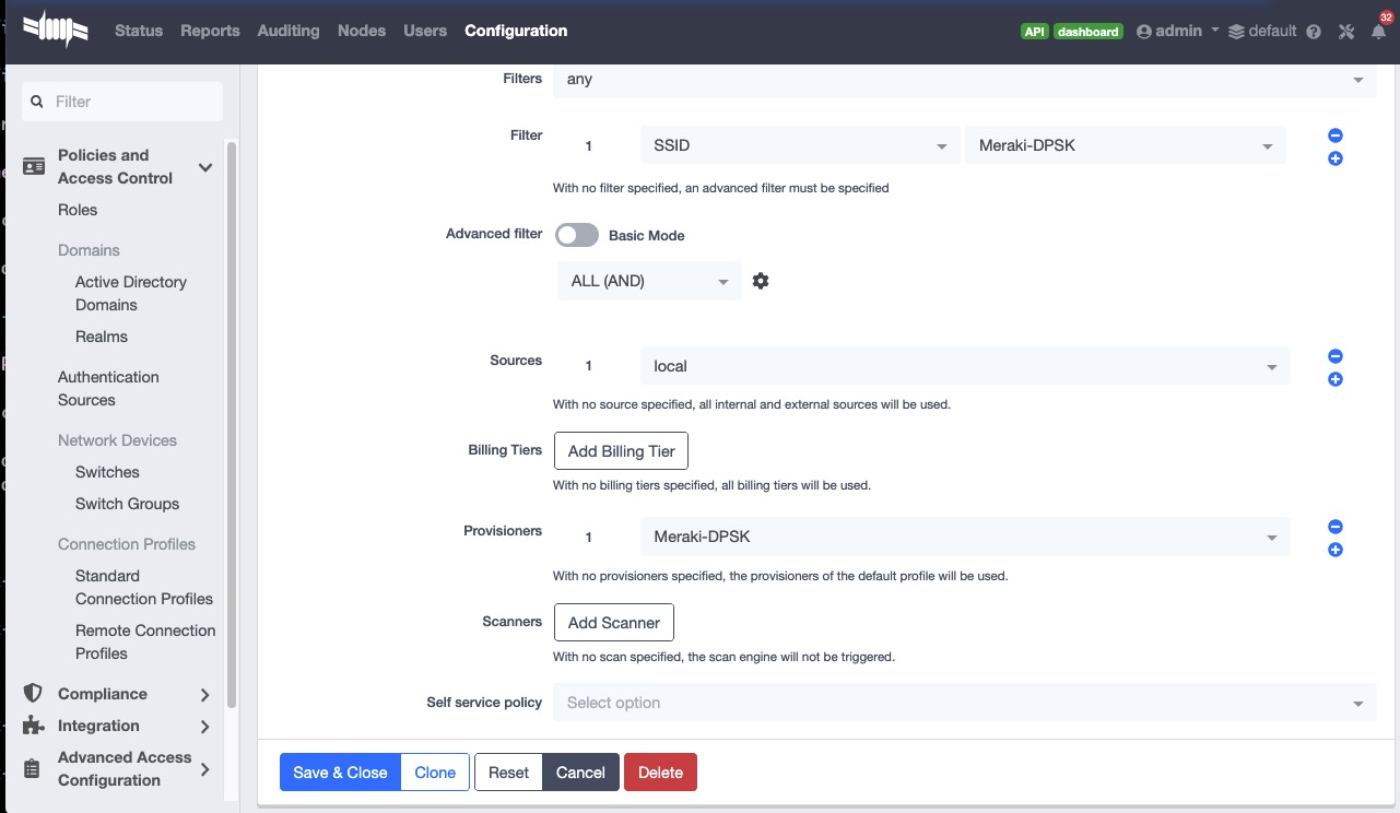
MS Switch Modules
MS Modules This is a standard switch module designed to support all the legacy Meraki Switch series using MS version earlier than v15.x.
Meraki MSv15 MSv15 module is designed for the switch series operating on MS_OS v15. Furthermore, it inherits all functionalities from the old "MS220_8" module, making all the configurations below applicable to MSv15.
The Meraki switch offer configuration for VLAN enforcement only.
You will need to access the Meraki dashboard to configure your switch. When you reach it you will need first to create a policy. You can create a "MAC authentication bypass" or a "802.1X" policy. Depending if you want to authenticate user via dot1x or MAB. You cannot combine both neither use a fallback mode on the same port, each port with a policy applied will be exclusive to MAB or dot1x.
To access the policy creation go to 'Switching→Access Policies' in the Meraki dashboard menu. From there create a new policy, use the example below to create your policy.
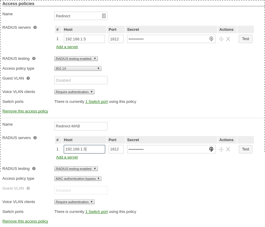
You now need to apply one of your policies to ports. To do so, go to
'Switch→Switch ports' and chose your options. To add a policy you created
earlier, select it in the drop down list in Access policy. You need to
configure the port in "mode access", the default access VLAN is not important if
your VLANs are properly configured on PacketFence.
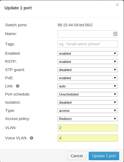
RADSEC
It is possible to use RADSEC between Meraki and PacketFence in order to perform RADIUS over TCP and encrypted using TLS. Before performing the steps outlined in this section, make sure you have a working SSID using normal unencrypted RADIUS by following the steps in the sections above
Then, in order to enable RADSEC, go in your SSID configuration and under 'RADIUS proxy', select 'Use Meraki proxy' and save the settings.
After saving, check the RADSEC checkbox and save your settings.
Now, on your PacketFence server, you must add the Meraki CA root to the trusted Certificate Authorities of FreeRADIUS when performing RADSEC. You should download the Meraki CA certificate from your Meraki dashboard under Organization→Configure→Certificates and selecting "Download CA" below RadSec AP Certificates. You can then append the content of this certificate to /usr/local/pf/raddb/certs/ca.pem on your PacketFence server.
Next, restart radiusd to reload the CA certificates using:
# /usr/local/pf/bin/pfcmd service radiusd restart
4.20. Mikrotik
PacketFence supports MikroTik’s RouterOS to provide wireless 802.1X (WPA2-Enterprise and MAC-based authentication) as well as wired 802.1X (EAPoL (Extensible Authentication Protocol over LAN)).
MikroTik has supported wireless 802.1X RADIUS disconnect for 2+ years, but this is not available for wired 802.1X (dot1x).
This configuration has been tested on a variety of MikroTik devices, including RB433AH, hAP ac, hAP ac lite, RB1100, RB3011 and various CCR devices. MikroTik provide free software updates ('/system package update install' and then '/sys routerboard upgrade' after booting new RouterOS).
Default MikroTik de-auth method has been changed to RADIUS, instead of SSH. Change 'my $default = $SNMP::RADIUS;' back to 'my $default = $SNMP::SSH;' if you want to continue using SSH as the de-authentication method.
EAPoL (802.1X) wired authentication has been available since v6.46 (Dec 2019) with MAB fallback being stable in v6.48.3.
PS: Don’t forget to use the pf account to ssh on the Access Point, to receive the ssh key, if you switch back to using SSH.
WPA2-EAP (WPA2 Enterprise) 802.1X SSID with MAC-based authentication on
WPA2-PSK SSID
In this example the 2.4 and 5 GHz radios are configured to provide wireless 802.1X with a virtual AP being added to provide MAC-based authentication on a WPA2-PSK SSID where the password is disclosed as part of the SSID. Although the Pre-Shared Key (PSK) is published each wireless client’s connection would still be encrypted with a dynamically generated key.
First we create the SSIDs and virtual AP for the second SSID:
/interface wireless security-profilesadd authentication-types=wpa2-eap disable-pmkid=yes interim-update=15mmanagement-protection=allowed mode=dynamic-keys name=radius-eap \radius-eap-accounting=yes supplicant-identity=""add authentication-types=wpa2-psk disable-pmkid=yes eap-methods=""interim-update=15m management-protection=allowed mode=dynamic-keys name=\radius-mac radius-mac-accounting=yes radius-mac-authentication=yessupplicant-identity="" wpa2-pre-shared-key="internet"/interface wirelessset [ find default-name=wlan1 ] band=2ghz-b/g/n channel-width=20mhzcountry="south africa" disabled=no frequency=auto mode=ap-bridge name=\"wlan1 - 2.4 GHz - ACME WiFi" security-profile=radius-eapskip-dfs-channels=all ssid="ACME WiFi" station-roaming=enabledvlan-id=3999 \vlan-mode=use-tag wireless-protocol=802.11 wps-mode=disabledadd disabled=no master-interface="wlan1 - 2.4 GHz - ACME WiFi"multicast-helper=full name="wlan1 - 2.4 GHz - ACME Guest" \security-profile=radius-mac ssid="ACME Guest (pw: internet)"station-roaming=enabled vlan-id=3999 vlan-mode=use-tag wps-mode=disabledset [ find default-name=wlan2 ] band=5ghz-a/n/acchannel-width=20/40/80mhz-Ceee country="south africa" disabled=nofrequency=auto mode=ap-bridge \name="wlan2 - 5 GHz - ACME WiFi" security-profile=radius-eapskip-dfs-channels=all ssid="ACME WiFi" station-roaming=enabledvlan-id=3999 \vlan-mode=use-tag wireless-protocol=802.11 wps-mode=disabledadd disabled=no master-interface="wlan2 - 5 GHz - ACME WiFi"multicast-helper=full name="wlan2 - 5 GHz - ACME Guest" \security-profile=radius-mac ssid="ACME Guest (pw: internet)"station-roaming=enabled vlan-id=3999 vlan-mode=use-tag wps-mode=disabledPS: VLAN 3999 is purposefully bogus, to ensure no access without VLANassignment in the RADIUS response.
Next we create a VLAN filtering bridge:
/interface bridgeadd name=bridge vlan-filtering=yes/interface bridge portadd bridge=bridge interface="wlan1 - 2.4 GHz - ACME WiFi"add bridge=bridge interface="wlan2 - 5 GHz - ACME WiFi"add bridge=bridge interface="wlan1 - 2.4 GHz - ACME Guest"add bridge=bridge interface="wlan2 - 5 GHz - ACME Guest"/interface bridge vlanadd bridge=bridge tagged="bridge,wlan1 - 2.4 GHz - ACME WiFi,wlan2 - 5 GHz -ACME WiFi,wlan1 - 2.4 GHz - ACME Guest,wlan2 - 5 GHz - ACME Guest"vlan-ids=52add bridge=bridge tagged="bridge,wlan1 - 2.4 GHz - ACME WiFi,wlan2 - 5 GHz -ACME WiFi,wlan1 - 2.4 GHz - ACME Guest,wlan2 - 5 GHz - ACME Guest"vlan-ids=666add bridge=bridge tagged="bridge,wlan1 - 2.4 GHz - ACME WiFi,wlan2 - 5 GHz -ACME WiFi,wlan1 - 2.4 GHz - ACME Guest,wlan2 - 5 GHz - ACME Guest"vlan-ids=667
Next we create the VLANs and assign IPs:
/interface vlanadd comment="Guest WiFi:" interface=bridge name=vlan52 vlan-id=52add comment="PacketFence - Registration:" interface=bridge name=vlan666vlan-id=666add comment="PacketFence - Isolation:" interface=bridge name=vlan667vlan-id=667/ip addressadd address=172.16.20.1/24 interface=bridgeadd address=10.239.239.1/24 interface=vlan52add address=192.168.10.225/28 interface=vlan666add address=192.168.10.241/28 interface=vlan667PS: 172.16.20.1 is essentially assigned to VLAN 1 (untagged)
Last settings on the MikroTik defines PacketFence as the RADIUS server and filters traffic on Guest, Registration and Isolation networks:
/radiusadd address=172.16.5.17 comment=packetfence: secret=useStrongerSecretservice=wireless src-address=172.16.20.1 timeout=1s/radius incomingset accept=yes/ip dhcp-relayadd dhcp-server=172.31.31.1 disabled=no interface=vlan666local-address=192.168.10.225 add-relay-info=yes name="PacketFence -Registration"add dhcp-server=172.31.31.129 disabled=no interface=vlan667local-address=192.168.10.241 add-relay-info=yes name="PacketFence -Isolation"/ip firewall address-listadd address=10.0.0.0/8 list=localadd address=172.16.0.0/12 list=localadd address=192.168.0.0/16 list=local/ip firewall filteradd action=reject chain=forward comment="Limit WiFi - Guest:"dst-address=!41.1.1.1 dst-address-list=local in-interface=vlan52add action=reject chain=forward comment="Limit PacketFence - Registration:"dst-address=!172.31.31.1 in-interface=vlan666add action=reject chain=forward comment="Limit PacketFence - Isolation:"dst-address=!172.31.31.129 in-interface=vlan667PS: Use 'src-address' to originate requests from an IP other than the oneassociated with the interface that routes towards PacketFence.172.31.31.1 is PacketFence's routed registration network IP and172.31.31.129 is the routed Isolation IP.
PacketFence switch configuration:
/usr/local/pf/conf/switches.conf[default]guestVlan=52registrationVlan=666isolationVlan=667always_trigger=1_[group MikroTik]description=Default MikroTik SettingsdeauthMethod=RADIUStype=Mikrotikuplink_dynamic=0useCoA=N_[100.127.255.10]description=ACME - Home Office - Bargroup=MikroTikradiusSecret=useStrongerSecret
4.20.1. Wired 802.1X with MAB (MAC authentication bypass)
MikroTik calls this dot1x and is documented in more detail here: https://help.mikrotik.com/docs/display/ROS/Dot1X
The configuration requires a VLAN filtering bridge with Spanning Tree Protocol enabled. New bridges by default have RSTP (Rapid Spanning Tree Protocol) enabled, so you can follow similar steps as above for wireless 802.1X.
Set the PacketFence RADIUS server to be used for dot1x:
/radiusadd address=172.16.5.17 comment=packetfence: secret=useStrongerSecretservice=dot1x src-address=172.16.20.1 timeout=1s
Add the ethernet ports to the bridge:
/interface bridge portadd bridge=bridge interface=ether2add bridge=bridge interface=ether3add bridge=bridge interface=ether4add bridge=bridge interface=ether5PS: We use ether1 as our uplink, so we exclude it from the bridge.
Lastly we enable 802.1X for those interfaces, with MAB fallback:
/interface dot1x serveradd auth-types=dot1x,mac-auth interface=ether2 interim-update=15madd auth-types=dot1x,mac-auth interface=ether3 interim-update=15madd auth-types=dot1x,mac-auth interface=ether4 interim-update=15madd auth-types=dot1x,mac-auth interface=ether5 interim-update=15m
4.20.2. Open SSID
In this setup we use the interface ether5 for the bridge (Trunk interface) and ether1 as the management interface.
Configure your access point with the following configuration:
/interface wireless# managed by CAPsMAN# channel: 5180/20-Ce/an(17dBm), SSID: OPEN, local forwardingset [ find default-name=wlan1 ] band=5ghz-a/n channel-width=20/40mhz-Cedisabled=no l2mtu=1600 mode=ap-bridge ssid=MikroTik-05A64D/interface ethernetset [ find default-name=ether1 ] name=ether1-gatewayset [ find default-name=ether2 ] name=ether2-master-localset [ find default-name=ether3 ] master-port=ether2-master-localname=ether3-slave-localset [ find default-name=ether4 ] master-port=ether2-master-localname=ether4-slave-localset [ find default-name=ether5 ] name=ether5-master-local/interface vlanadd interface=BR-CAPS l2mtu=1594 name=default vlan-id=1add interface=BR-CAPS l2mtu=1594 name=isolation vlan-id=3add interface=BR-CAPS l2mtu=1594 name=registration vlan-id=2/caps-man datapathadd bridge=BR-CAPS client-to-client-forwarding=yes local-forwarding=yes name=datapath1/caps-man interface#add arp=enabled configuration.mode=ap configuration.ssid=OPEN datapath=datapath1 disabled=no l2mtu=1600 mac-address=\D4:CA:6D:05:A6:4D master-interface=none mtu=1500 name=cap1 radio-mac=D4:CA:6D:05:A6:4D/caps-man aaaset interim-update=5m/caps-man access-listadd action=query-radius interface=cap1 radius-accounting=yes signal-range=-120..120 time=0s-1d,sun,mon,tue,wed,thu,fri,sat/caps-man managerset enabled=yes/interface bridge portadd bridge=bridge-local interface=ether2-master-localadd bridge=bridge-local interface=ether1-gatewayadd bridge=BR-CAPS interface=ether5-master-local/interface wireless capset bridge=BR-CAPS discovery-interfaces=BR-CAPS enabled=yes interfaces=wlan1/ip accountingset enabled=yes/radiusadd address=192.168.1.5 secret=useStrongerSecret service=wireless/radius incomingset accept=yes
4.20.3. Webauth
You can use webauth (external captive portal) on Mikrotik APs. In order to do so, you will have to activate the hotspot feature in the AP configuration as well as modify the redirection template so that it points to PacketFence.
First, you must establish an FTP connection to your access point and replace the
content of hotspot/login.html with the following:
<html><head><title>...</title></head><body>$(if chap-id)<noscript><center><b>JavaScript required. Enable JavaScript to continue.</b></center></noscript>$(endif)<center>If you are not redirected in a few seconds, click 'continue' below<br><form name="redirect" action="http://192.168.1.5/Mikrotik" method="get"><input type="hidden" name="mac" value="$(mac)"><input type="hidden" name="ip" value="$(ip)"><input type="hidden" name="username" value="$(username)"><input type="hidden" name="link-login" value="$(link-login)"><input type="hidden" name="link-orig" value="$(link-orig)"><input type="hidden" name="error" value="$(error)"><input type="hidden" name="chap-id" value="$(chap-id)"><input type="hidden" name="chap-challenge" value="$(chap-challenge)"><input type="hidden" name="link-login-only" value="$(link-login-only)"><input type="hidden" name="link-orig-esc" value="$(link-orig-esc)"><input type="hidden" name="mac-esc" value="$(mac-esc)"><input type="hidden" name="ap-id" value="AP_IP_ADDRESS_HERE"><input type="submit" value="continue"></form><script language="JavaScript"><!--document.redirect.submit();//--></script></center></body></html>
Next, in the login.html you have just uploaded, make sure you change
AP_IP_ADDRESS_HERE by the management IP address of your access point and
192.168.1.5 by the IP address of your PacketFence captive portal.
Now, you must configure the hotspot feature on your AP. This configuration is
done on top of an existing SSID you have previously configured which is on
interface wlan1. Adjust the interface name if needed.
/ip hotspotsetup
hotspot interface: wlan1
local address of network: 10.5.50.1/24masquerade network: yes
Set pool for HotSpot addresses
address pool of network: 10.5.50.2-10.5.50.254
Select hotspot SSL certificate
select certificate: none
Select SMTP server
ip address of smtp server: 0.0.0.0
Setup DNS configuration
dns servers: 8.8.8.8
DNS name of local hotspot server
dns name: myhotspot
Create local hotspot user
name of local hotspot user: adminpassword for the user:
Next, you need to allow access to the PacketFence portal in the hotspot access
list. Change 192.168.1.5 with the IP address you pointed to in login.html
/ip hotspot walled-gardenadd dst-host=192.168.1.5add src-address=192.168.1.5
/ip hotspot walled-garden ipadd action=accept disabled=no dst-host=192.168.1.5add action=accept disabled=no src-address=192.168.1.5
Now, you will also need to configure the hotspot to point to your PacketFence RADIUS server:
/radiusadd address=192.168.1.5 secret=useStrongerSecret service=hotspot
/ip hotspot profileadd hotspot-address=10.5.50.1 name=hsprof1 use-radius=yes
Next, you need to configure PacketFence to use webauth for this Access Point
using the following switches.conf configuration. Change AP_IP_ADDRESS_HERE
by the IP address you’ve put in login.html.
[AP_IP_ADDRESS_HERE]VlanMap=YRoleMap=Nmode=productionExternalPortalEnforcement=Ytype=MikrotikradiusSecret=useStrongerSecretregistrationVlan=-1
4.21. HP
4.21.1. ProCurve Controller MSM710
To be contributed...
4.22. Intelbras
4.22.1. AP3620
General Radius:
dot1x authentication-method eap
radius scheme packetfenceprimary authentication 192.168.1.5primary accounting 192.168.1.5key authentication simple useStrongerSecretkey accounting simple useStrongerSecretuser-name-format without-domain
radius dynamic-author serverclient ip 192.168.1.5 key simple useStrongerSecret
domain packetfenceauthentication default radius-scheme packetfenceauthorization default radius-scheme packetfenceaccounting default radius-scheme packetfence
interface WLAN-Radio1/0/2service-template pf-secureservice-template pf-openmax-power 22channel band-width 20
Secure 802.1x SSID:
wlan service-template pf-securessid PF-Secureakm mode dot1xcipher-suite ccmpsecurity-ie rsnclient-security authentication-mode dot1xdot1x domain dot1xbss transition-management enableservice-template enable
Open Mac-Authentication SSID:
wlan service-template pf-opendescription Captive portal authenticationssid !PF-Openclient-security authentication-mode macmac-authentication domain packetfenceservice-template enable
4.23. Meru
4.23.1. Meru Controllers (MC)
In this section, we cover the basic configuration of the Meru wireless controller for PacketFence via the controller web interface.
Disable PMK Caching
If you are running a WPA2 SSID, you may need to disable PMK caching in order to avoid deauthentication issues. This is true if you are running AP 300s using any 5.0 versions including 5.0-87, or any versions below 4.0-160.
Here are the commands to run to disable the PMK caching at the AP level. First, login the AP, and run this command to see which radios are broadcasting your SSID. vap display
Second, disable the PMK caching on those radios. radio pmkid radio00 disable
You can also add those commands to the AP bootscript. Contact your Meru support representative for that part.
VLAN Definition
Here, we create our PacketFence VLANs for client use. Go to Configuration → Wired → VLAN, and select Add.
- VLAN Name is the human readable name (ie. RegistrationVLAN)
- Tag is the VLAN ID
- Fast Ethernet Interface Index refers to the controller’s ethernet interface
- IP Address – An IP address for this controller on this VLAN
- Netmask – Network mask for this VLAN
- IP Address of the default gateway – Wired IP router for this VLAN
- Set the Override Default DHCP server flag to off
- Leave the DHCP server IP address and the DHCP relay Pass-Through to default
Click OK to add the VLAN.
AAA Authentication Server
Here, we create our PacketFence RADIUS server for use. Under Configuration → Security → Radius, select Add.
- Give the RADIUS Profile a name
- Write a description of the profile
- Give the RADIUS IP, RADIUS Secret and the RADIUS authentication port
- Select Colon for the MAC address delimiter
- Select MAC Address as the password type
Click OK to add the RADIUS profile.
AAA Accounting Server
Here, we create our PacketFence RADIUS server for use. Under Configuration → Security → Radius, select Add.
- Give the RADIUS Profile a name
- Write a description of the profile
- Give the RADIUS IP, RADIUS Secret and the RADIUS accounting port
- Select Colon for the MAC address delimiter
- Select MAC Address as the password type
Click OK to add the RADIUS accounting profile.
AAA Profiles – Open SSID
Here, we create our wireless security profiles for use. Under Configuration → Security → Profile, select Add.
- Give the security profile a name
- Select Clear as the L2 Modes Allowed
- Leave Data Encrypt empty
- Disable the Captive Portal
- Enable the Mac Filtering
Click OK to save the profile.
MAC Filtering
When using the OpenSSID, you need to activate the mac filtering. Under Configuration → Mac Filtering:
- Set ACL Environment State to Permit list enabled
- Select your RADIUS profile
AAA Profiles – Secure SSID
Here, we create our wireless security profiles for use. Under Configuration → Security → Profile, select Add.
- Give the security profile a name
- Select WPA2 as the L2 Modes Allowed
- Select CCMP-AES for Data Encrypt
- Select your PacketFence RADIUS Authentication Profile
- Disable the Captive Portal
- Enable the 802.1X network initiation
- Leave the Mac Filtering to off
Click OK to save the profile.
WLAN SSIDs
Here, we create our SSID and tie it to a security profile. Under Configuration → Wireless → ESS, select Add.
- Give the ESS profile a name, and enable it
- Write an SSID name
- Select your security profile name previously created
- Select your PacketFence RADIUS Accounting Profile (if you want to do accounting)
- Enable the SSID Broadcast
- Make the new AP to join the ESS
- Set the tunnel interface type to RADIUS and Configured VLAN
- Select the registration VLAN for the VLAN Name
Click OK to create the SSID. Repeat those steps for the open and secure SSID by choosing the right security profile.
WLAN SSIDs – Adding to access point
Here, we tie our SSIDs to access points. Under Configuration → Wireless → ESS, select the SSID you want to add to your aps. Then, select the ESS-AP Table, and click Add.
- Select the AP ID from the drop down list
- Click OK to associate the SSID with this AP
Roles (Per-User Firewall)
Since PacketFence 3.3, we now support roles (per-user firewall rules) for the Meru hardware. To add firewall rules, go in Configuration → QoS System Settings → QoS and Firewall Rules. When you add a rule, you have to pay attention to two things:
- The rule is applied to the controller physical interface right away, so make sure you are not too wide on your ACL to lock you out!
- The rules are grouped using the Firewall Filter ID (We will use this ID for the roles)
So, since the matching is done using the Firewall Filter ID configuration field, your roles line in switches.conf would look like :
roles=Guests=1;Staff=2
4.24. Mojo Networks
PacketFence supports SSIDs configured with 802.1X and Web Authentication
4.24.1. Create the RADIUS Profile
First, create a RADIUS Profile for PacketFence.
- Login to the https://dashboard.mojonetworks.com
- Go to Wireless Manager
-
Then click on Configuration → Device Configuration → RADIUS Profiles →
Add a RADIUS Profile
Profile Name: NAME_OF_PROFILE_FOR_PACKETFENCEIP Address: IP_OF_PACKETFENCEAuthentication Port: 1812Accounting Port: 1813Shared Secret: useStrongerSecret
Click on 'Save'.
4.24.2. Configure the SSID:
802.1X Secure
- Login to the https://dashboard.mojonetworks.com
- Go to Wireless Manager
- Then click on Configuration → Device Configuration → SSID Profiles → Add a new Profile → WLAN
Profile Name: PF-Secure-802.1XSSID: PF-SecureSecurity: WPA2; 802.1XNAS ID: %m-%sDynamic VLANs: Enable VLAN Pool 1,2,4,5 (All VLANs that you will use)Called-Station-ID: %m-%sCOA: Checked
RADIUS AuthenticationPrimary Authentication Server: PacketFence RADIUS profile created above.
RADIUS Accounting Server DetailsPrimary Accounting Server: PacketFence RADIUS profile created above.
Click the 'Save' button to save the PF-Secure SSID configuration.
Web Authentication
To enable the external captive portal, go to the SSID Profiles page in Device Configuration. Add a new Wi-Fi profile with the following attributes:
Profile Name: Name of the new profileSSID: Name of your SSIDSecurity: Open
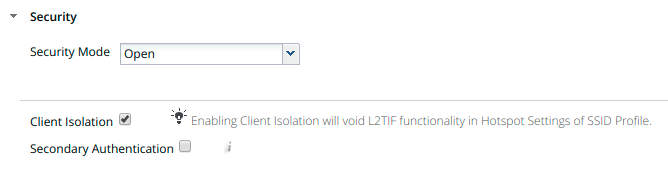
Network: VLAN ID for clients
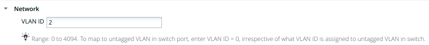
Captive Portal: select and fill in External Splash Page with RADIUSAuthentication with “http://IP_OR_HOSTNAME_OF_PACKETFENCE/Mojo” and theRADIUS shared secret. Click on *RADIUS Settings* to select PacketFence asauthentication and accounting server.
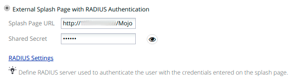
On the right, add the IP address or hostname of PacketFence to the WalledGarden Sites.
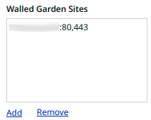
Save the newly created profile.
4.24.3. Broadcast the SSID on the Access Point:
- Go to Configuration → Device Template → System Template
- Then Radio Settings → Define settings for model → Chose your AP model
- Finally Radio 1 - 2x2 b/g/n Configuration → Add SSID Profile → Select your SSID profile previously created(802.1X or Web authentication profile) → Ok
Click the 'Save' button to broadcast the PF-Secure SSID.
4.24.4. Configure the Mojo Networks AP in PacketFence:
802.1X
Add a Switch with the IP address of the Access Point (AP) with the following configuration:
-
Go to Configuration → Network → Switches → Add switch to group → Default
Definition:IP Address/MAC Address/Range (CIDR): Local IP of the APDescription: Mojo Networks Access PointType: Mojo Networks APMode: ProductionSwitch Group: NoneDeauthentication Method: RADIUSUse CoA: CheckedRoles:Role by VLAN ID: Checkedregistration: 2isolation: 3guest: 5default: 1NOTE: Role by VLAN ID remain the only category checked.Radius:Secret Passphrase: useStrongerSecret
Web Authentication
Add a switch with the IP address fo the Access Point (AP) with the following configuration:
-
Go to Configuration → Network → Switches → Add switch to group → Default
Definition:IP Address/MAC Address/Range (CIDR): Local IP of the APDescription: Mojo Networks Access PointType: Mojo Networks APMode: ProductionSwitch Group: NoneDeauthentication Method: RADIUSUse CoA: CheckedRoles:Uncheck Role by VLAN IDRadius:Secret Passphrase: useStrongerSecret
Click the 'Save' button to save the AP configuration.
4.25. Motorola
In order to have the Motorola RFS controller working with PacketFence, you need to define two Wireless LANs definition, one for the "public" network, and one for the "secure" network.
4.25.1. WiNG (Firmware >= 5.0)
AAA Policy (RADIUS server)
First, we need to build the AAA Policy. Under Configuration → Wireless → AAA Policy, click on the Add button at the bottom right. Configure the RADIUS profile like the following:
- Host: Choose IP Address in the drop down, and put the RADIUS server (PF) IP
- Insert a RADIUS secret passphrase
- Select "Through Wireless Controller" Request Mode
Open SSID
Under Configuration → Wireless → Wireless LANs, click on the Add button at the bottom right. Under Basic Configuration:
- Profile Name : Give a convenient name
- SSID: This is the ESSID name
- Ensure that the WLAN Status is set to enable
- Select Single VLAN as VLAN assignment technique
- Ensure that "Allow RADIUS Override" is selected
- Select MAC as authentication type
- Select your AAA Policy previously created
- Ensure that you selected Open as the Encryption
- Make sure you select "Enable RADIUS Accounting"
- Select the previously configured AAA Policy
- Make sure you select RADIUS Dynamic Authorization
Secure SSID
Under Configuration → Wireless → Wireless LANs, click on the Add button at the bottom right. Under Basic Configuration:
- Profile Name : Give a convenient name
- SSID: This is the ESSID name
- Ensure that the WLAN Status is set to enable
- Select Single VLAN as VLAN assignment technique
- Ensure that "Allow RADIUS Override" is selected
- Select EAP as authentication type
- Select your AAA Policy previously created
- Ensure that you selected WPA/WPA2-TKIP as the Encryption
- Unselect everything under Fast Roaming (Disable caching)
- Make sure you select "Enable RADIUS Accounting"
- Select the previously configured AAA Policy
- Make sure you select RADIUS Dynamic Authorization
Profile (WLAN Mapping)
You have multiple options here. Either, you create a general AP profile, and you assign it to your Aps, or you modify the AP device configuration to map the WLAN to the radio interfaces. For the purpose of this document, we will modify the general profile. Under Profiles → default-apXXX (where XXX is your AP model), in Interface → Radios, edit the existing radios settings. Go to the WLAN Mapping tab, select the two SSIDs and click on the << button.
Profile (Management)
Here, we can configure our SNMP community strings. Located in Configuration → Management → Management Policy. Again, you can modify the default one, or you can create a brand new Policy.
VLANs
You need to ensure that the uplink interface of the controller is configured as a trunk, and that all the necessary VLANs are created on the device. This is configured under Device → rfsXXXX-MAC (where XXXX is your controller series, and MAC is the latest 3 octets of its mac address). Edit the device configuration, and go to Interface → Ethernet Ports. Ensure that the up1 interface is set as trunk, with all the allowed VLANs. Next, create the VLAN under Interface → Virtual Interfaces.
Roles (Per-User Firewall)
Since PacketFence 3.3, we now support roles for the Motorola hardware using WiNGS 5.x. To add roles, go in Configuration → Security → Wireless Client Roles. First create a global policy that will contain your roles. Next, create your Roles by clicking on the Add button on the bottom right. It is important to configure the Group Configuration line properly by setting the string name that we will use in the RADIUS packet. For example, for a Guests Role, you can put Group Configuration Exact Guests, and for a Staff Roles, you can put Group Configuration Exact Staff. In the roles configuration in switches.conf, you would have something like :
roles=CategoryGuests=Guests;CategoryStaff=Staff
Finally, don’t forget to configure the appropriate firewall rules for your Roles! Make sure also to commit the configuration upon your changes.
WIPS
In order to enable the WIPS functionality on the Motorola, you need to follow this procedure. The steps have been done using the CLI.
First, Create a wips-policy:
wips-policy Rogue-APhistory-throttle-duration 86400event ap-anomaly airjackevent ap-anomaly null-probe-responseevent ap-anomaly asleapevent ap-anomaly ad-hoc-violationevent ap-anomaly ap-ssid-broadcast-in-beaconevent ap-anomaly impersonation-attackap-detection
Next, create an event policy:
event-system-policy PF-WIDSevent wips wips-event syslog off snmp on forward-to-switch off email off
Next, create or adjust your management policy to configure the SNMP traps. Here is an example policy, please note the two last lines:
management-policy defaultno http serverhttps serversshuser admin password 1e4c93663e3356787d451312eeb8d4704ef09f2331a20133764c3dc3121f13a5b rolesuperuser access alluser operator password 17c9b1fbb2ed7d5bb50dba0b563eac722b0676b45fed726d3e4e563b0c87d236d role monitoraccess allno snmp-server manager v3snmp-server community public rosnmp-server community private rwsnmp-server user snmpoperator v3 encrypted des auth md5 0 operatorsnmp-server user snmptrap v3 encrypted des auth md5 0 motorolasnmp-server user snmpmanager v3 encrypted des auth md5 0 motorolasnmp-server enable trapssnmp-server host 10.0.0.100 v2c 162
You then need to tell your controller to use the event policy:
rfs6000 5C-0E-8B-17-F2-E3...use event-system-policy PF-WIDS
Finally, you need to configure a radio interface on your AP to act as a sensor. Here is an example configuration for a dual-radio AP650:
ap650 00-23-68-86-EB-BCuse profile default-ap650use rf-domain defaulthostname ap650-86EBBCcountry-code cause wips-policy Rogue-APinterface radio1rf-mode sensorchannel smartpower smartdata-rates defaultno preamble-shortradio-share-mode offinterface radio2...
4.25.2. Older Firmwares (< 5.0)
- Check the Dynamic Assignment check-box
- Select "MAC Authentication" under Authentication
- Click "Config…" choose the Colon delimiter format
- Un-check all encryption options
- Under RADIUS put in PacketFence’s RADIUS Server information
- Check the Dynamic Assignment check-box
- Select "802.1X EAP" under Authentication
- Check WPA/WPA2-TKIP encryption option
- Under RADIUS put in PacketFence’s RADIUS Server information
SNMP Global configuration
Add the two Read-Only and Read-Write users under Management Access → SNMP Access.
4.26. Ruckus
AAA Servers
We need to define the RADIUS and RADIUS accounting (mandatory):
Under Configuration → AAA Servers, click on the Create New button. Enter the proper configuration:
- Enter a server name
- Select either RADIUS or RADIUS accounting as the type
- Use PAP as the Auth Method
- Enter the IP address, and shared secret.
- Hit OK
Repeat the steps for the RADIUS and RADIUS accounting types. We need 1 definition for each otherwise RADIUS dynamic authorization won’t work.
WLAN Definitions
Under Configuration → WLAN, click on the Create New button. Enter the proper configuration:
- Enter a Name/SSID
- Select Standard Usage as the Type
- Select MAC Address as the authentication type
- Select Open as the encryption method
- Select the proper RADIUS server as the authentication server
- Select the proper RADIUS server as the accounting server
- Enter a Name/SSID
- Select Standard Usage as the Type
- Select WPA2 as the authentication type
- Select AES as the encryption method
- Select the proper RADIUS server as the authentication server
- Select the proper RADIUS server as the accounting server
- Check the Enable Dynamic VLAN checkbox
WIPS
To enable the WIPS feature of the Ruckus in order to send SNMP traps to PacketFence, the setup is fairly simple.
First, configure the controller to send the traps to PacketFence. Under Configure → System → Network Management → SNMP Trap:
*Select "Enable SNMP Trap" *Put the PacketFence Management IP in the Trap Server IP field
Next, you need to configure the Alarm Settings. Under Configure → Alarm Settings, make sure the following are selected:
*Rogue AP Detected *SSID-Spoofing AP Detected *MAC-Spoofing AP Detected *LAN Rogue AP Detected
Finally, enable the WIPS feature on the controller. Under Configure → WIPS → Intrusion Detection and Prevention, make sure both box are selected, click Apply.
4.26.1. Web Authentication
In order to use PacketFence as an external captive portal for web authentication, you will need to configure first your RADIUS authentication and accounting server (see steps above).
Hotspot configuration
Configure the Hotspot service profile to redirect devices to your PacketFence portal. Go on the ZoneDirector administration web page to the section Configure→Hotspot Services→Create New
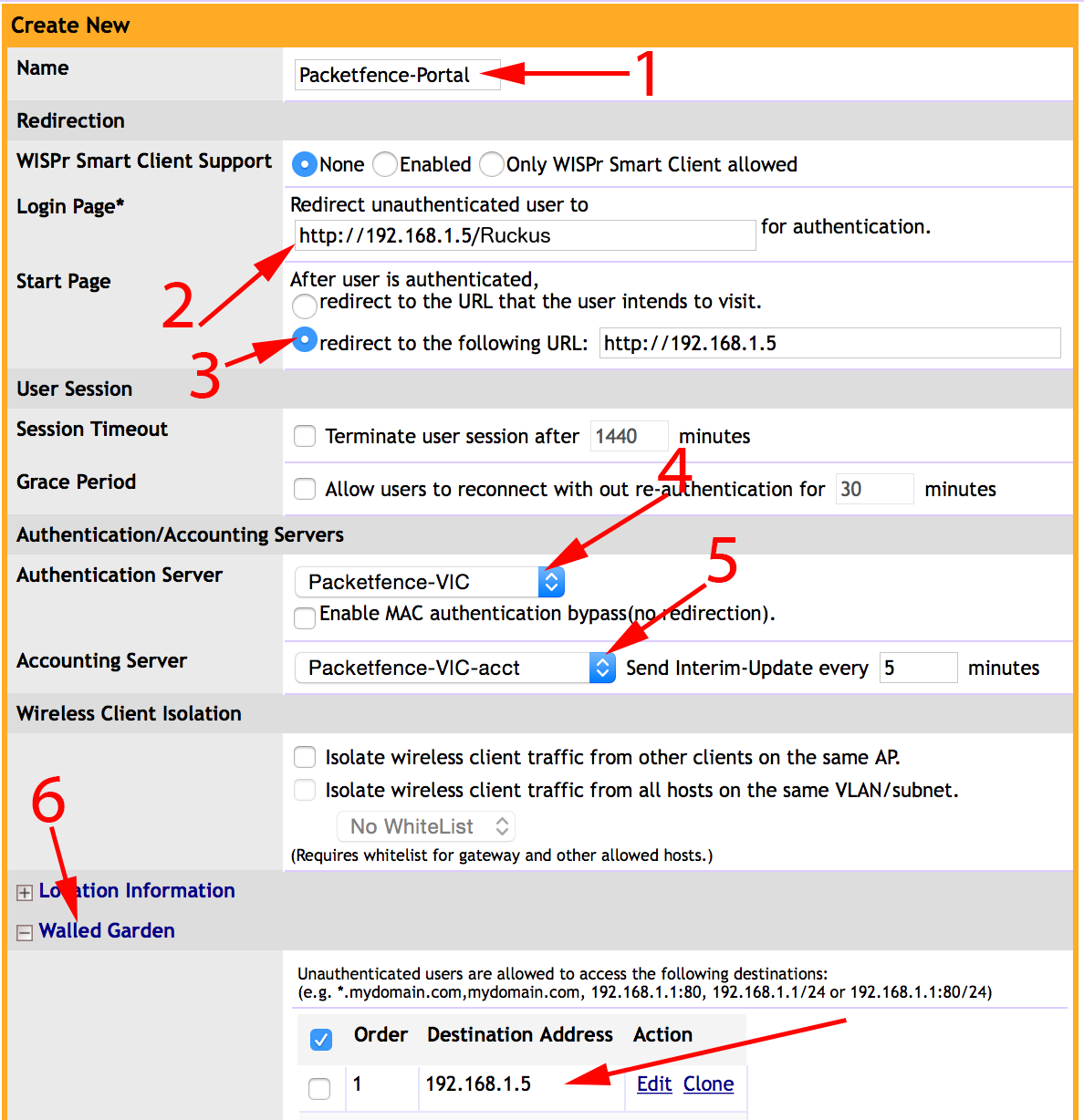
1 - Name of your Hotspot service2 - Login Page: Url of PacketFence portal interface (http://192.168.1.5/Ruckus)3 - Start Page: redirect to the following URL: http://192.168.1.54 - Authentication Server: Select the PacketFence authentication RADIUS server(default port 1812)5 - Accounting Server: Select the PacketFence accounting RADIUS server (default1813)6 - Click on the Walled Garden and authorize the IP of PacketFence managementinterface
Save your configuration.
WLAN configuration
Go to Configure → WLANs → WLANs → Create New
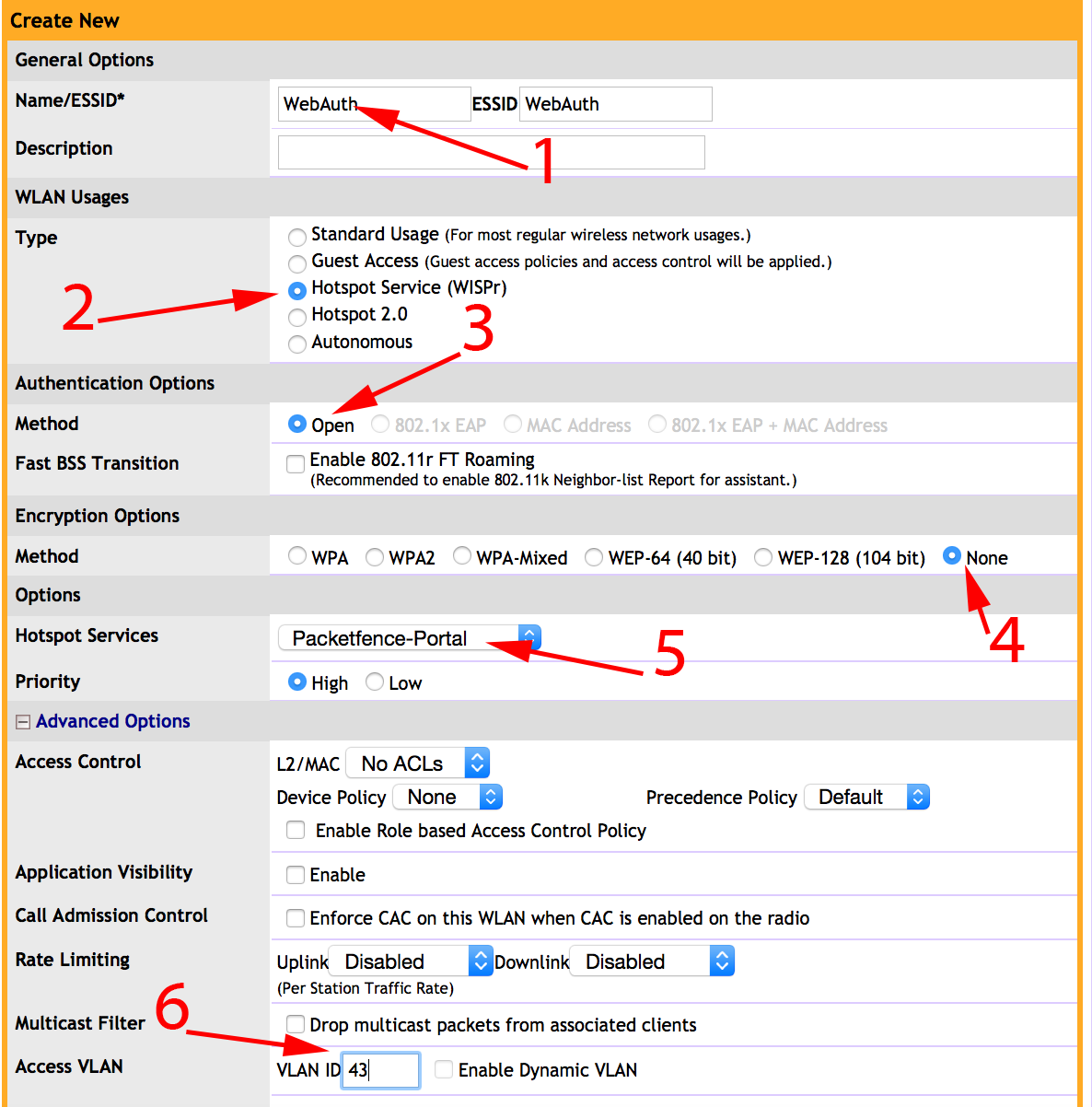
1 - Name of your SSID2 - Type: Hotspot Service (WISPr)3 - Authentication Method: Open4 - Encryption Method: None5 - Hotspot Services: Your hotspot service name that you configured6 - Access VLAN: The VLAN ID that should be assigned to devices afterauthentication
Save your configuration.
PacketFence configuration
On the ZoneDirector configuration in PacketFence, you will need to specify -1 as the registration VLAN in order to display the captive portal to the end device.
You will need to deactivate the force secure redirect on the captive portal under Configuration → Captive Portal → Secure redirect → Unchecked
The captive portal needs to listen on the management interface, so you will need to add the portal daemon to the management interface under Configuration → Interfaces → Management Interface
Example:
[interface eth0]ip=192.168.1.5type=management,portalmask=255.255.255.0
To apply the configuration, restart PacketFence using the following command:
service packetfence restart
4.26.2. Ruckus Roles
Roles Configuration
Ruckus allows you to define roles. These roles link all users to the internal WLAN and permit access to all WLAN by default. You can still limit access to certain WLAN. Additionally, these roles can be used to apply per-user rate-limits and ACLs in newer versions of the Zone Director firmware, specifying also advanced options like Application Recognition Policies, URL filtering profiles, Etc.
To create a new user Role:
1 - Go to _Admin & Services -> System -> Roles_. The Roles page appears,displaying a Default role in the Roles table.2 - Click Create New.3 - Enter a Name and a short Description for this role.4 - Choose the options for this role from the following:Group Attributes: Fill in this field only if you are creating a user rolebased on Group attributes extracted from an Active Directory server. Enterthe User Group name here. Active Directory/LDAP users with the same groupattributes are automatically mapped to this user role.Allow All WLANs: You have two options: (1) Allow Access to all WLANs, or (2)Specify WLAN Access. If you select the second option, you must specify theWLANs by clicking the check box next to each one.
The images below show the steps needed for Ruckus Unleashed.
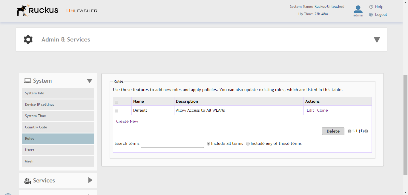
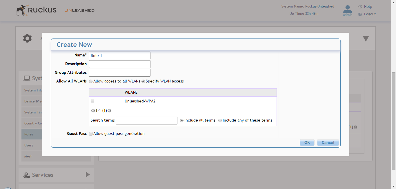
If using ZoneDirector, then the steps are very similar as shown below:
To create a new user Role:
1 - Go to _Services & Profiles -> Roles_. The Roles and Policies page appears,displaying a Default role in the Roles table.2 - Click Create New.3 - Enter a Name and a short Description for this role.4 - Choose the options for this role from the following:Group Attributes: Fill in this field only if you are creating a user rolebased on Group attributes extracted from an Active Directory server.Enter the User Group name here. Active Directory/LDAP users with the samegroup attributes are automatically mapped to this user role.Allow All WLANs: You have two options: (1) Allow Access to all WLANs, or (2)Specify WLAN Access. If you select the second option, youmust specify the WLANs by clicking the check box next to each one. Don'tenable the "Guest Pass" or "Administration" options as theseallow users with the given Roles to get administrative access to theZoneDirector console.5 - Additionally, you can enable the "Role Based Access Control Policy" optionwhich is the most interesting one from PacketFence's point of view,since this allows specific PF roles to receive specific ACLs, Different ratelimits, thus further enhancing the value of Packetfence.6 - Looking at the RBAC Policy options one can define the following:OS type: Limit access based on operating system/device type.VLAN: Assign a VLAN ID to this role. (This can be overriden directly fromPacketFence if using the _Role by VLAN ID_ option)Rate Limiting: Limit per-station uplink and downlink speeds.L3/L4/IP address ACL: Apply a Layer 3/Layer 4/IP address ACL to this role.Application Recognition & Control: Apply an application policy to this role.Time Range: Limit the time range during which this role will be allowed toaccess the WLAN.7 - Finally, if using the RBAC feature in ZoneDirector, make sure to enable theRBAC functionality for the WLAN created before:To do this, edit the WLAN, expand the Advanced Options, and enable the checkbox next to Enable Role Based Access Control Policy in the Access Controlsection.
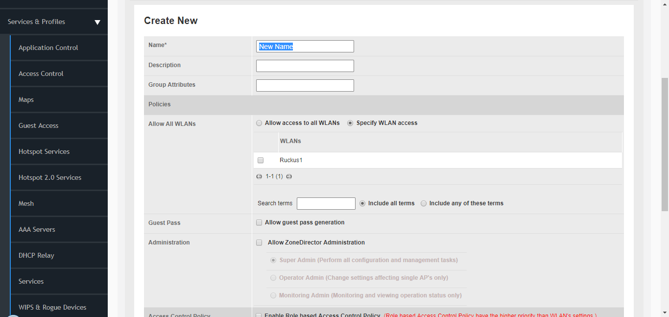
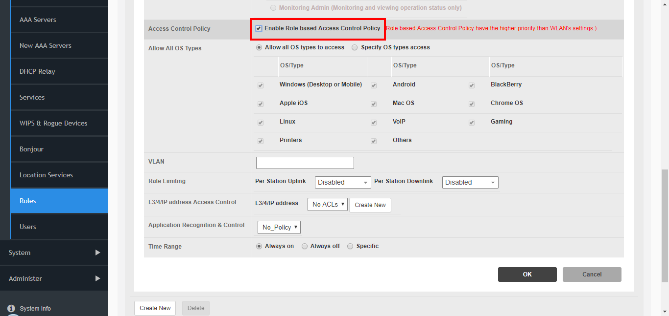
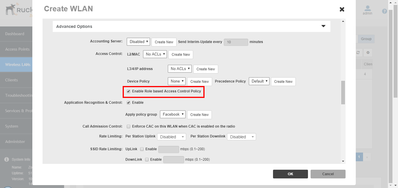
PacketFence Configuration
On the PacketFence side you need to use role by switch role and add the same name as in the Group Attribute you created on the Ruckus side.
When a device connects to the SSID, PacketFence will return a VLAN identifier and a RuckusUserGroup attribute and if the role is allowed on the WLAN then the device will be authorized on the WLAN. Additionally, if RBAC is in use, the specific upstream/downstream rate limits, L2/L3 ACLS and Application Recognition Policies will be applied to the specific user, having the possibility of, for instance, giving different user Roles different access speeds. In case that the role is not allowed on the WLAN then the device will not be allowed to connect.
4.27. Ruckus SmartZone
Ruckus SmartZone is extremely flexible and allows for very different deployment scenarios, with the controller being an "on-premise" appliance managing a single tenant as well as a cloud-hosted solution where multiple tenants can share a single SmartZone instance by using its "managed partner domains" capabilities (For SmartZone-Highscale). As such, when it comes to AAA capabilities, the RADIUS connection between Ruckus and PacketFence supports two modes of operation: PROXY mode and non-PROXY mode.
In Proxy Mode, all RADIUS connections are done between SmartZone and PacketFence. In this mode, the RADIUS interface supports the use of Disconnect and CoA messages sent from PacketFence (the RADIUS server) to SmartZone (The RADIUS client). If proxy mode is used, it is highly recommended to have SmartZone deployed locally in the LAN together with PacketFence as otherwise, it might be needed to open specific ports (RADIUS COA/Disconnect ports) for PacketFence to be able to reach SmartZone if SmartZone is in a cloud scenario. Additionally, this would also mandate PacketFence to be hosted behind a static public IP, which is not always the case for certain business ISPs, as this IP would need to be configured in SmartZone as the target RADIUS IP.
In non-PROXY mode, though, the AP can send the RADIUS Access Request directly to PacketFence. This allows for SmartZone to be hosted in a public cloud. In this case, though, only an immediate response to the Access Request message can be issued by PacketFence and accepted by the AP. As clients can be roaming betwen APs, RADIUS CoA or Disconnect messages are not supported since the client might no longer be connected to the targetted AP. In this case, PacketFence must rely insted in the WISPr web services to trigger a disconnection / VLAN move after authentication.
In short, if hosting a SmartZone appliance (physical or virtual) inside the LAN and PacketFence and SmartZone can talk directly without extraneous port-maps, use the PROXY mode for RADIUS as its much simpler. But if using a shared or external SmartZone server while keeping PacketFence local to the LAN, then opt for the NON-PROXY mode.
4.27.2. SmartZone configuration
First, define the RADIUS server in Configuration → Service and Profiles → Authentication. In newer versions (at least Firmware 3.6) make sure to select the proper RADIUS model (proxy or non-proxy according to the deployment details as described above)
Create the server using the following information (where 192.168.1.5 is the IP address of the PacketFence management interface):
- 'IP Address:' 192.168.1.5
- 'Port': 1812
- 'Secret': useStrongerSecret
Then, in Configuration → Service and Profiles → Accounting, create a server with the following information:
- 'IP Address:' 192.168.1.5
- 'Port': 1813
- 'Secret': useStrongerSecret
After, create a Hotspot in Configuration → AP Zones → Zone → Hotspot WISPr → Create New. Adjust 192.168.1.5 to the IP address of the portal.
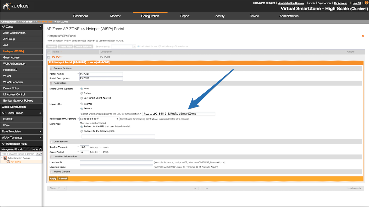
Then, still on this page, in the 'Walled Gardens', make sure to add the portal IP address in this list.
Next, configure the WLAN to use the Hotspot authentication and point it to PacketFence. Also ensure 'Use the controller as a proxy' is set.
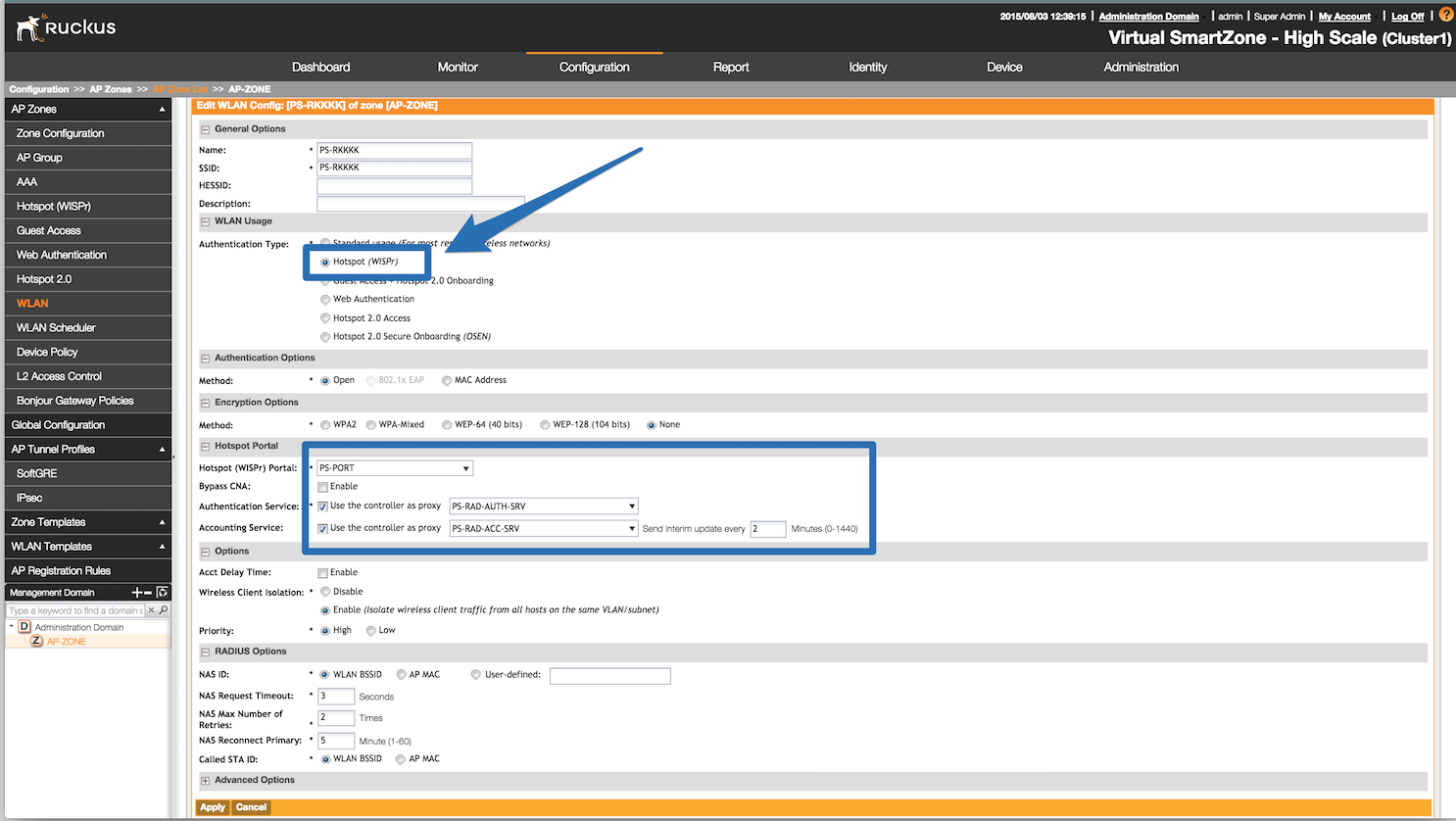
Now, configure the Northbound API of the SmartZone so PacketFence can
communicate with it. In order to do so, go in
Configuration → System → Northbound Portal Interface (Can be called "WISPr
Northbound Interfaces" in newer versions of SmartZone)
and set the 'Password' and save it. Keep the password closeby as it will be
required for the PacketFence configuration. In this
example, it will be passwordForNorthboundAPI. In case of using a SmartZone
High-scale, define a northbound
username/password for each Managed Domain so that each customer can
have their own credentials. In this case, define
both a username and password and keep both closeby.
In order to receive the information not encrypted in the URL, connect to the Ruckus SmartZone controller using SSH and execute the following command:
no encrypt-mac-ip
4.27.3. PacketFence configuration
In PacketFence, add a new switch in Configuration → Switches with the following configuration:
- Definition → External Portal Enforcement should be enabled
-
Definition → Type:
Ruckus SmartZone Wireless Controller -
Definition → Mode:
production -
Definition → Controller IP Address:
IP address of SmartZone controller - Roles → Role by VLAN ID should be enabled
-
Roles → registration VLAN:
-1 - Roles → Role by Switch Role can be optionally enabled (see below)
-
RADIUS → Secret passphrase:
useStrongerSecret -
Web Services → Username:
usernameForNorthboundAPI -
Web Services → Password:
passwordForNorthboundAPI
The Web Services Username is optional and only needed if using the "Managed Partner Domains" feature of SmartZone with multiple different Northbound API credentials (one per SmartZone domain). Additionally, for troubleshooting purposes, one can define the Web Services → Transport to HTTP instead of the default HTTPS so as to simplify troubleshooting by capturing the traffic between PacketFence and SmartZone.
4.27.4. Mac Authentication
For MAC authentication there are two options. Using SmartZone as a proxy RADIUS server (where all RADIUS requests are sent between the SmartZone controller and PacketFence directly) and non-radius RADIUS where the APs send RADIUS messages directly to PacketFence. This non-proxy scenario is useful when both the APs and PacketFence are "inside the LAN" but the SmartZone controller is in the WAN (for example, hosted in a commercial cloud provider). In this case, direct communication between SmartZone and PacketFence might not be possible as the WAN IP for PacketFence might be dynamic.
4.27.6. SmartZone configuration
First, define the RADIUS server in Service and Profiles → Authentication. Then select the "Proxy (SZ Authenticator)" tab and then select the zone for which to create the AAA server.
Create the server using the following information (where 192.168.1.5 is the IP address of the PacketFence management interface):
- 'Name' : PacketFence-Auth
- 'Service Protocol': RADIUS
- 'IP Address:' 192.168.1.5
- 'Port': 1812
- 'Secret': useStrongerSecret
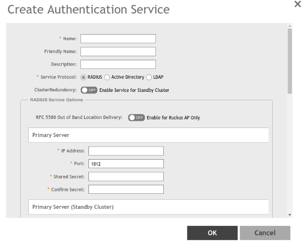
Then, in Service and Profiles → Accounting. Then select the "Proxy" tab and then select the zone for which to create the AAA server. Create the server using the information below:
- 'Name' : PacketFence-Acct
- 'IP Address:' 192.168.1.5
- 'Port': 1813
- 'Secret': useStrongerSecret
Give both authentication and accounting services an easily identifiable name such as "PacketFence-Auth" and "Packerfence-Acct". This names are purely for identification purposes only.
Now create an SSID with OPEN/MAC athentication.
In the Wireless LANs top level menu , from the System tree hierarchy, select the Zone where to create a WLAN and then click Create.
Enter the name and SSID, then for Authentication Type select "Standard Usage" and for Method select "MAC Address".
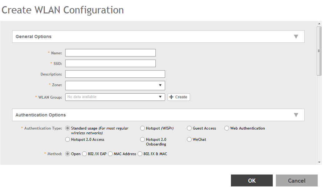
The rest of the authentication options can be left "as-is" (The default MAC Address Format of "aabbccddeeff" should work fine)
For the Authentication & Accounting Service enable the "Use controller as proxy" checkbox for both Authentication and Accounting and select the previously created Authentication and Accounting profiles. (PacketFence-Auth and PacketFence-Acct respectively if the names suggested above)
Finally in the Advanced Options section, under Access VLAN section, make sure to enable the Enable Dynamic VLAN (AAA Override) checkbox is enabled so that the client receives a VLAN assigned by PacketFence.
4.27.7. PacketFence configuration
In PacketFence, add a new switch in Configuration → Switches with the following configuration:
- Definition → External Portal Enforcement should NOT be enabled
-
Definition → Type:
Ruckus SmartZone Wireless Controller -
Definition → Mode:
production - Definition → Use CoA: Can be enabled
- Definition → Controller IP Address: IP address of SmartZone controller
-
Definition → CoA Port:
3799 - Roles → Role by VLAN ID should be enabled
- Roles → registration VLAN: The registration VLAN ID
- Roles → isolation VLAN: The isolation VLAN ID
- Roles → Role by Switch Role can be optionally enabled (see below)
-
RADIUS → Secret passphrase:
useStrongerSecret
4.27.8. Non-PROXY mode
For non-proxy MAC authentication, repeat the same configuration as for PROXY mode but create the Authentication and Accounting servers under the "Non-Proxy (AP Authenticator)" menu. Additionally, configure the "WISPr northbound credentials" as for the Webauth section. Only the username / password is required, no other configuration is needed (portals, etc)
4.27.9. PacketFence configuration
In PacketFence, add a new switch in Configuration → Switches with the following configuration:
- Definition → External Portal Enforcement should NOT be enabled
-
Definition → Type:
Ruckus SmartZone Wireless Controller -
Definition → Mode:
production -
Definition → Deauthentication Method:
HTTPS - Definition → Controller IP Address: IP address of SmartZone controller
- Roles → Role by VLAN ID should be enabled
- Roles → registration VLAN: The registration VLAN ID
- Roles → isolation VLAN: The isolation VLAN ID
- Roles → Role by Switch Role can be optionally enabled (see below)
-
RADIUS → Secret passphrase:
useStrongerSecret -
Web Services → Transport:
HTTPS -
Web Services → Username:
usernameForNorthboundAPI -
Web Services → Password:
passwordForNorthboundAPI
During troubleshooting, change the Deauth method and Web Services Transport to HTTP instead of HTTPS to capture the traffic destined to the SmartZone’s IP on port 9080 to inspect the WISPr API calls if needed.
For NON-PROXY Auth mode when using MAC-Authenticatin we need to set the "Deauthentication Method" to HTTP or HTTPS since this will force the disconnect message to be sent using the Northbound WISPr API instead of RADIUS Disconnect / CoA. If the Deauthentication Method is not set, then the code will try to use RADIUS by default and fail to disconnect the user.
4.27.10. Ruckus Roles
Roles Configuration
Ruckus SmartZone allows defining roles for RBAC purposes. They can be used to apply per-user rate-limits and ACLs in newer versions of the SmartZone firmware, specifying also advanced options like Application Recognition Policies, URL filtering profiles, (Firwewall profiles)
To create and be able to use the role, we need to perform several steps:
1 - Create a _User Traffic Profile_2 - Create a matching _User Role_3 - Reference the User Role in the RADIUS Authentication server
The detailed steps are as follow:
Go to Services & Profiles → Access Control on the left menu and then click on the User Traffic tab. On this page, optionally select a Domain/Zone, click the "Create" button and give the new UTP name. Define any additional parameters such as Uplink/Downlink rate limits, define any ACLs that might be needed for that role and also select, if needed, an Application Recognition and Control policy and URL Filtering Control policies.
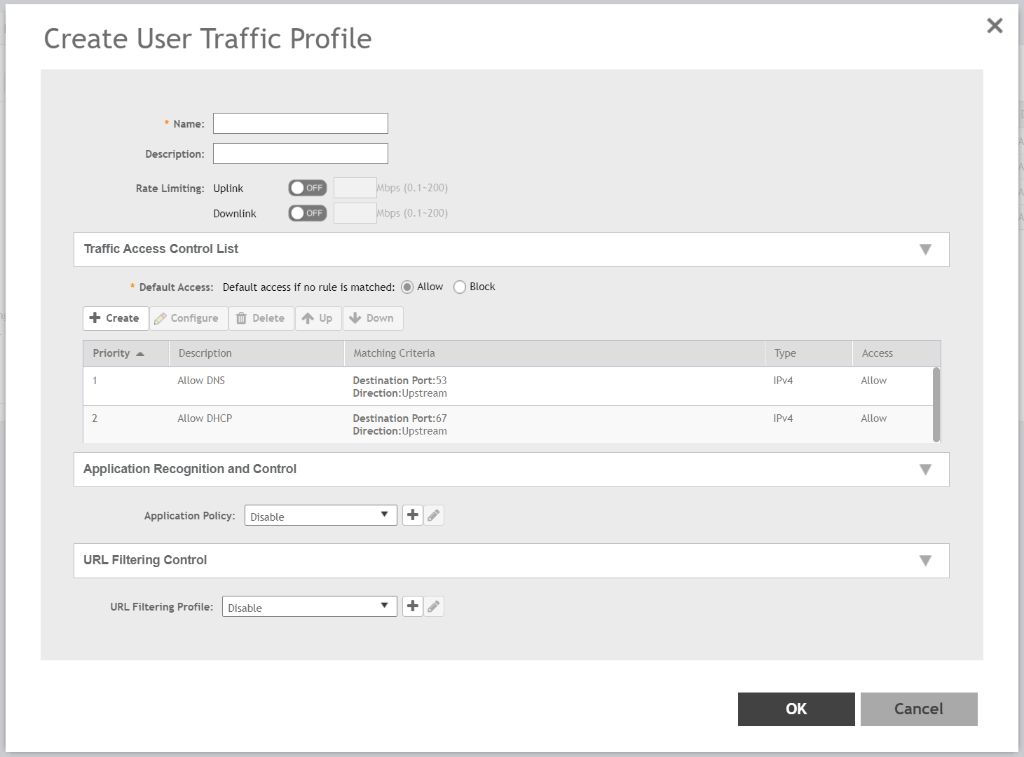
Next, go to Clients → Users & Roles menu and select the User Roles tab. On this page, optionally select a Domain/Zone, click the "Create" button and give the new User Role a name. This name is purely for identification only and its not the RADIUS attribute. Choose any meaningful name. Also select the User Traffic Profile defined in the previous step as well as, optionally, a Firewall Profile.
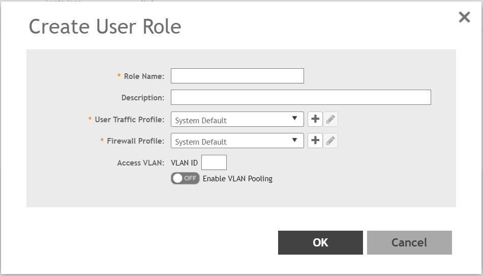
Finally, under Configuration → Service and Profiles → Authentication, select the RADIUS server created previously (Either in Proxy or NON-Proxy mode). Then, under the User Role Mapping section, click on Create.
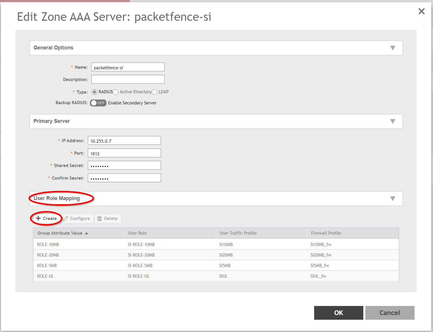
A new window will open where we can create a "User Traffic Profile Mapping". Under Group Attribute Value enter the string that will be sent from PacketFence (Configured under the Switch configuration in the "Role by Switch Role" section). This string must match between PacketFence and SmartZone and is the string sent in the RADIUS reply under the Ruckus-User-Group VSA. Then, under the "User Role", select the previously created User Role.
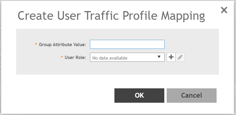
Repeat all the steps above for as many different roles as needed. Keep in mind that different roles can be defined on SmartZone than those on PacketFence. For example, on SmartZone there might be roles called "10Mbps", "20Mbps" and so on (related to the specific rate limits assigned to the users) and then in PacketFence, assign the "10Mbps" SmartZone role to the "Students" and "Guests" PacketFence Roles, and the "20Mbps" SZ role to "Faculty" and "IT" PF roles.
PacketFence Configuration
On the PacketFence side use role by switch role and add the same name as in the Group Attribute created on the Ruckus side.
So when a device connects to the SSID, PacketFence will return a VLAN identifier and a RuckusUserGroup attribute and the device will be authorized on the WLAN on the specific VLAN. Additionally, if RBAC is in use, the specific upstream/downstream rate limits, L2/L3 ACLS and Application Recognition Policies will be applied to the specific user, having the possibility of, for instance, giving different user Roles different access speeds.
4.28. Ruckus Unleashed
Web Authentication
In order to use PacketFence as an external captive portal for web authentication, you will need to first configure your RADIUS authentication and accounting server (see steps above).
Hotspot configuration
Create a new Wi-Fi network, define the SSID name, select Usage Type as "Hotspot Service", the Authentication Method to "Open" and the Encryption Method to "None".
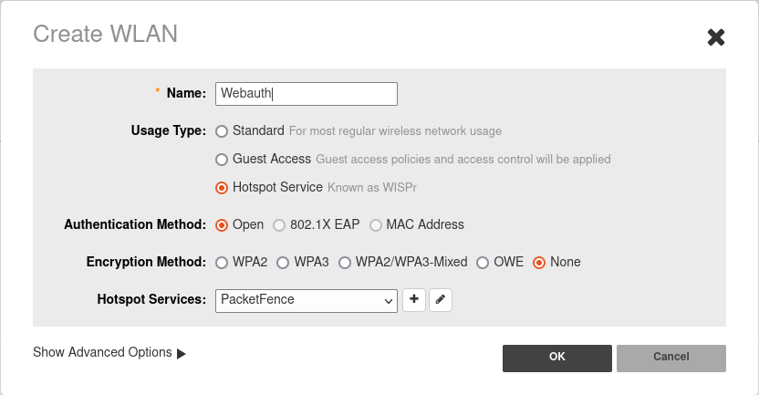
Configure the Hotspot service profile to redirect devices to your PacketFence portal. Click on the + next tro Hotspot Services.
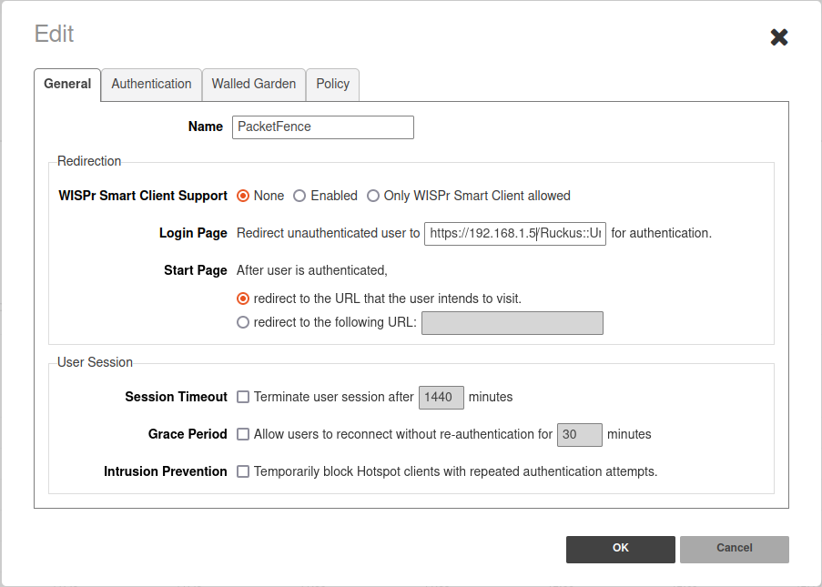
1 - Name of your Hotspot service2 - Login Page: URL of PacketFence portal interface(http://192.168.1.5/Ruckus::Unleashed)3 - Start Page: redirect to the URL that the user intends to visit.
In the Authentication Tab, click + next to Authentication server and define the RADIUS server.
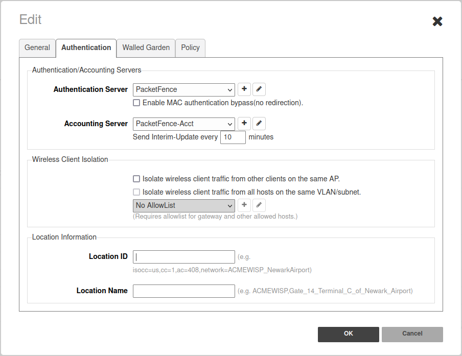
In the Authentication Tab, click + next to Accounting server and define the RADIUS server.
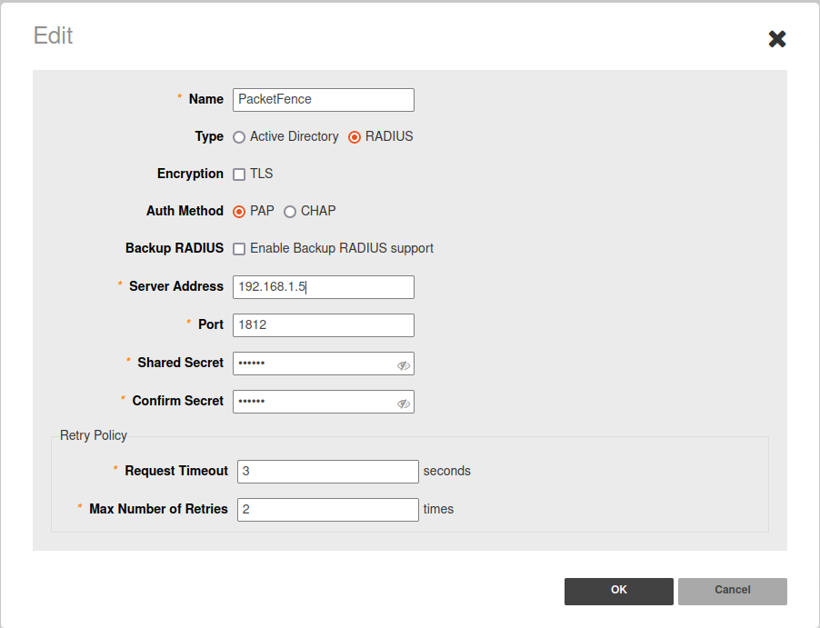
Save your configuration.
4.28.1. MAC Authentication
- Enter a Name/SSID
- Select Standard as the Type
- Select MAC Address as the authentication method
- Select Open as the encryption method
- Select the proper RADIUS server as the authentication server
- Select the proper RADIUS server as the accounting server
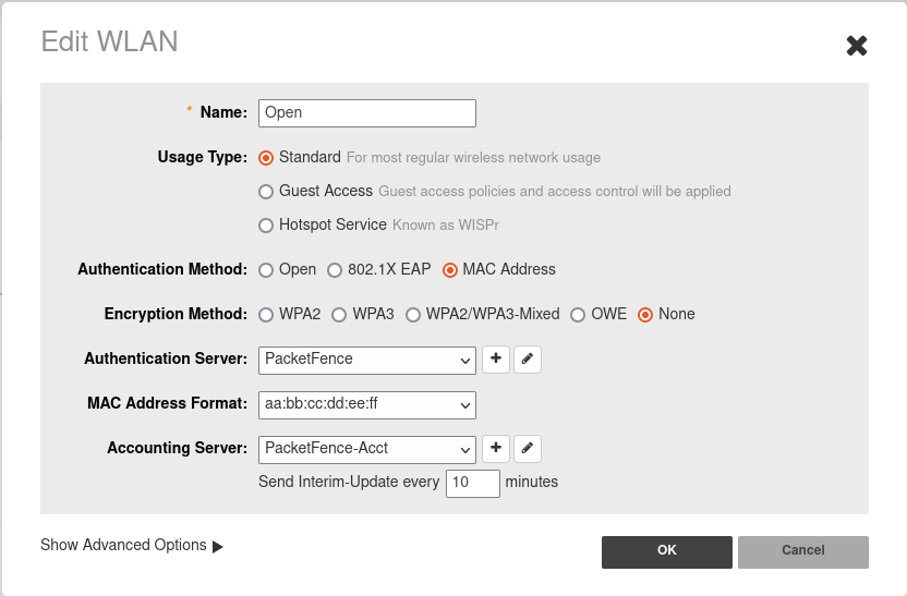
4.28.2. 802.1X Configuration
- Enter a Name/SSID
- Select Standard as the Type
- Select 802.1X EAP as the authentication method
- Select WPA2 as the encryption method
- Select the proper RADIUS server as the authentication server
- Select the proper RADIUS server as the accounting server
- In Advanced Options → WLAN Priority check "Enable Dynamic VLAN"
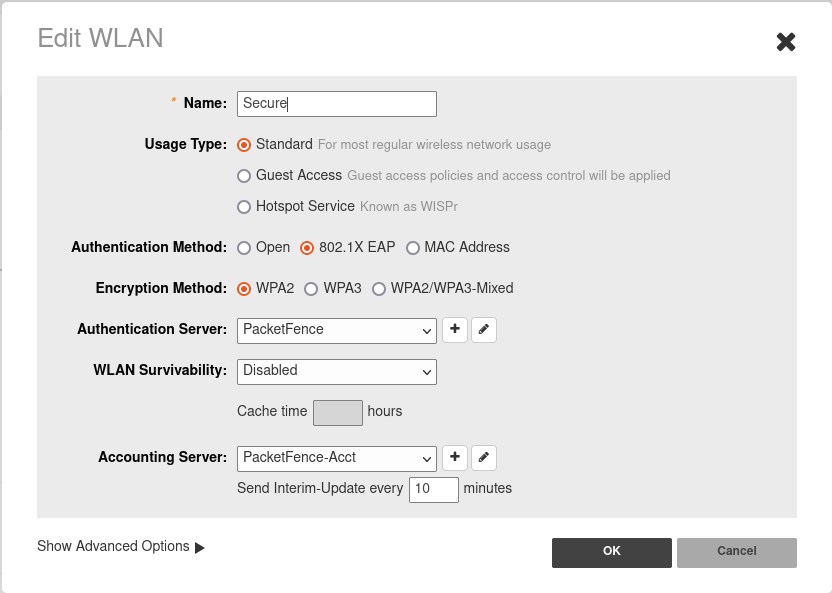
4.29. Trapeze
In order to have the Trapeze controller working with PacketFence, you need to define the RADIUS configuration and the proper service profiles.
RADIUS configuration
set radius server PF address 192.168.1.5 timeout 5 retransmit 3 deadtime 0 keysecretset server group PF-RADIUS members PF
Service Profiles
Here we define two service profiles, one for the open SSID (PacketFence-Public) and one for the WPA2-Enterprise SSID (PacketFence-Secure):
set service-profile PF-Open ssid-name PacketFence-Publicset service-profile PF-Open ssid-type clearset service-profile PF-Open auth-fallthru last-resortset service-profile PF-Open cipher-tkip enableset service-profile PF-Open auth-dot1x disableset service-profile PF-Open 11n mode-na requiredset service-profile PF-Open attr vlan-name WLAN_REGset service-profile PF-Secure ssid-name PacketFence-Secureset service-profile PF-Secure cipher-tkip enableset service-profile PF-Secure cipher-ccmp enableset service-profile PF-Secure wpa-ie enableset service-profile PF-Secure rsn-ie enableset service-profile PF-Secure 11n mode-na requiredset service-profile PF-Secure attr vlan-name Wlanset radio-profile default service-profile PacketFence-Publicset radio-profile default service-profile PacketFence-Secure
AAA configuration
Finally, we need to tie the service profiles with the proper AAA configuration.
set accounting dot1x ssid PacketFence-Secure ** start-stop PF-RADIUSset accounting mac ssid PacketFence-Public * start-stop PF-RADIUSset authentication mac ssid PacketFence-Public * PF-RADIUSset authentication dot1x ssid PacketFence-Secure ** pass-through PF-RADIUS
4.30. Ubiquiti
4.30.1. Web Authentication
Unifi side
In order to configure web authentication (external captive-portal) on Ubiquiti access points, you must have access to a Unifi controller and your APs must be connected to it.
First, you must configure the guest policy. Go in Settings → hotspot → general and configure it as shown below:
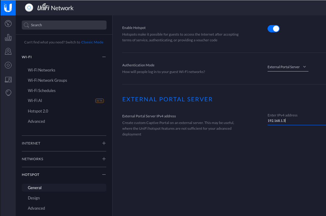
Next, you must allow the device to reach the portal. Go in Settings → hotspot → advanced and configure it as shown below:
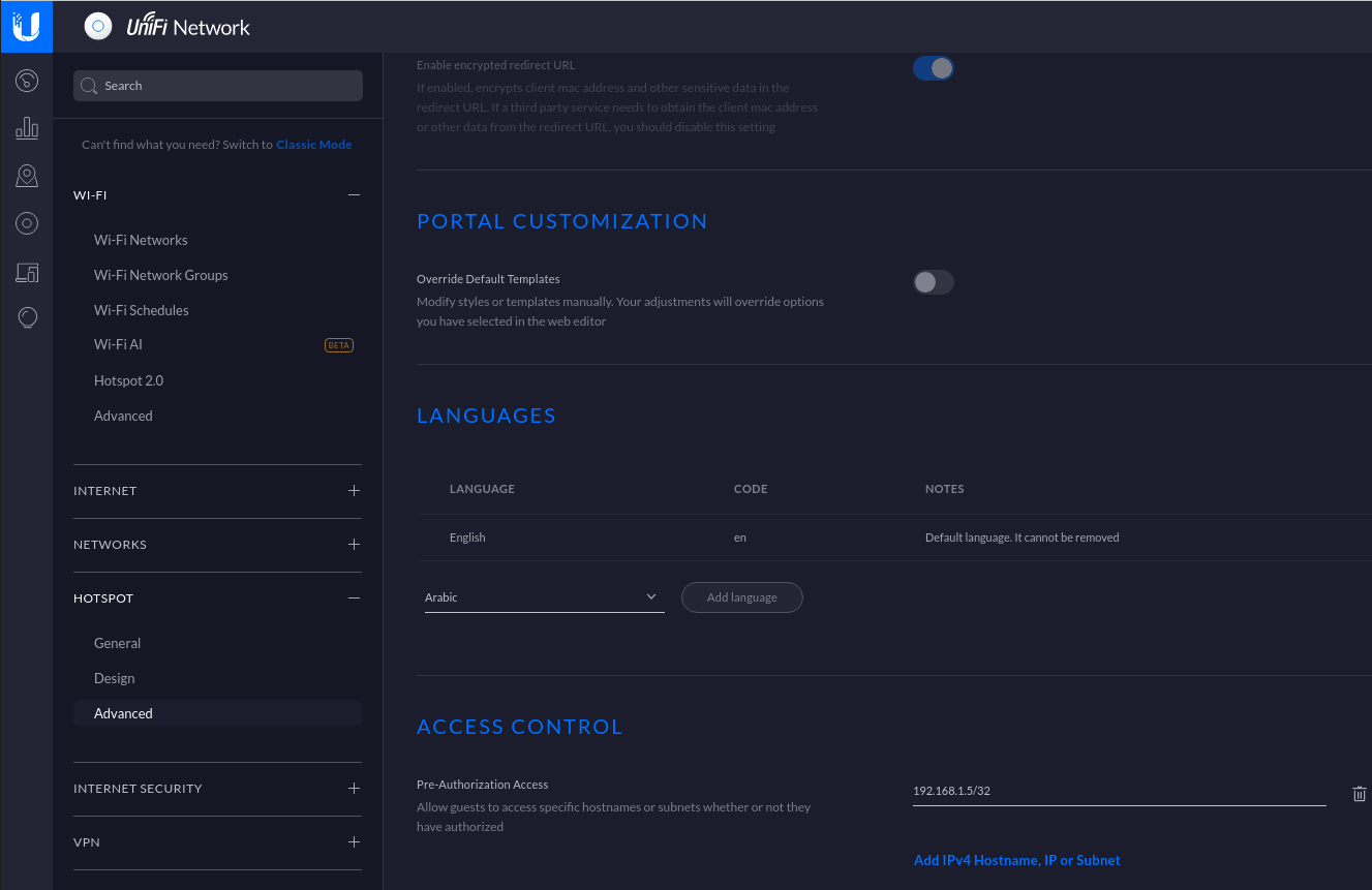
Make sure you enabled Enable Guest Portal, and that you’ve set External portal server.
You also need to enter the IP address of a portal enabled interface on the PacketFence server in Custom Portal. Then in the ACCESS CONTROL section, add that same IP address to the Pre-Authorization Access
Then, still in the settings, create or edit a new SSID with the following settings:
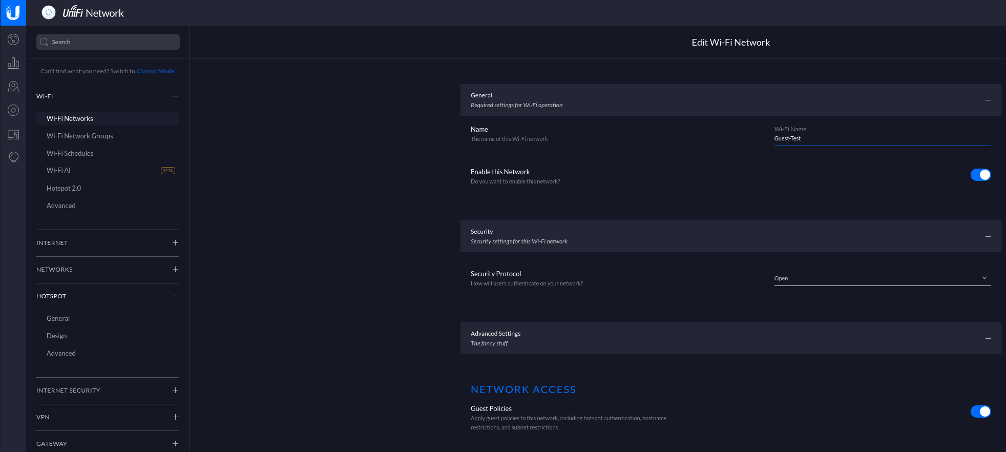
You need to ensure STUN protocol is allowed between access points and controller so that controller gets instant notifications from access points. That’s important to have a correct deauthentication mechanism.
PacketFence side
You have two choices to define the APs in PacketFence, by ip address (or range) or by MAC addresses.
By IP address:
If you decide to define the AP by ip then you will need to define the controller as a switch and define the Controller IP and Webservices information (Transport/Username/Password) in his configuration.
Then once done, restart pfcron service and run that to fill the PacketFence cache:
/usr/local/pf/bin/pfcmd pfcron ubiquiti_ap_mac_to_ip
And verify that you have an entry for each AP
/usr/local/pf/bin/pfcmd cache switch_distributed list
By MAC address:
Once this is done, you will need to define all your APs MAC addresses in the PacketFence switches with a configuration similar to this:
[00:11:22:33:44:55]description=Ubiquiti APExternalPortalEnforcement=Ytype=Ubiquiti::UnificontrollerIp=1.2.3.4wsTransport=HTTPSwsUser=adminwsPwd=admin
Where :
- wsTransport is the protocol used to connect to port 8443 of the Unifi controller and should be HTTPS. This is configured in the 'Web Services' tab of the switch.
- wsUser is a valid administrator username on your Unifi controller. This is configured in the 'Web Services' tab of the switch.
- wsPwd is the password that is associated to the wsUser. This is configured in the 'Web Services' tab of the switch.
- controllerIp is the IP address of your Unifi controller. This is configured in the 'Definition' tab of the switch.
4.30.2. VLAN Enforcement
In order to configure VLAN enforcement on the Unifi controller, you need first to configure a RADIUS profile, then a secure wireless network.
Important : You cannot reuse a VLAN ID for dynamic VLAN if it is set as a static value for another SSID on the same AP. So, if you have a SSID set to use VLAN 10, you cannot use VLAN ID 10 for RADIUS controlled VLAN users as those users will not get an IP address.
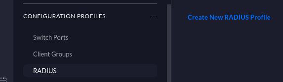
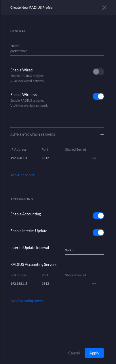
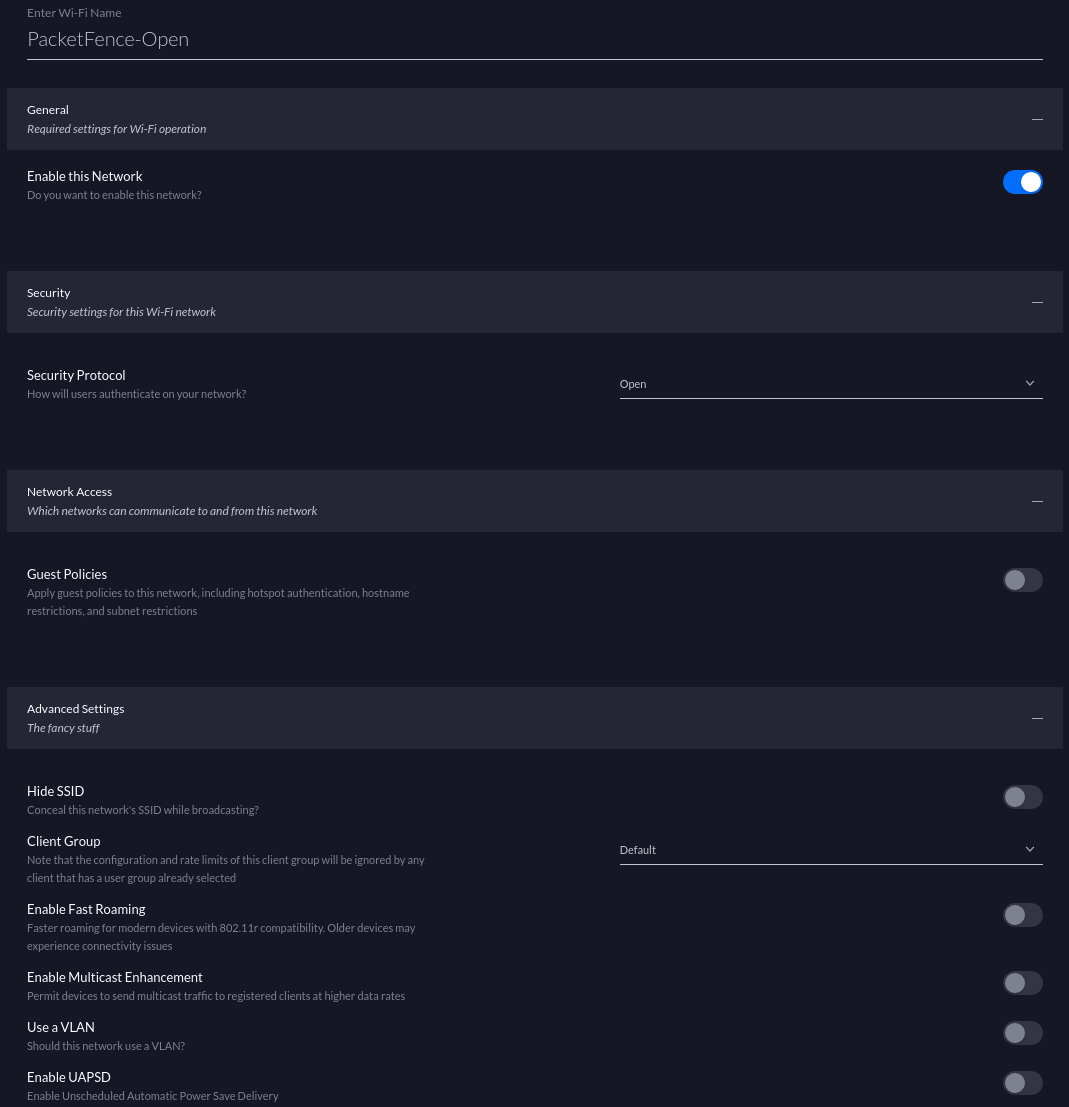
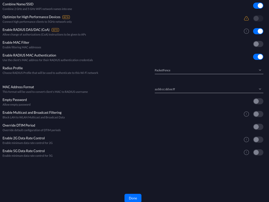
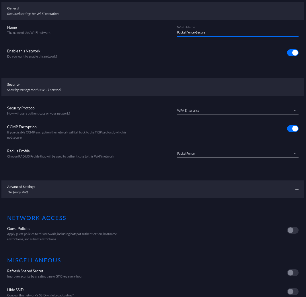
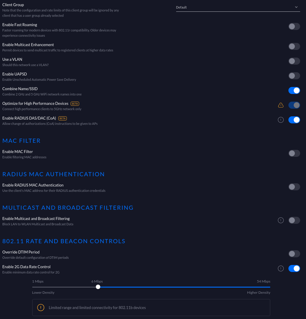
CoA Support
CoA support has been introduced in the new version of the controller (Tested on 5.13.10), so on access reevaluation if you selected RADIUS as disconnect method then PacketFence will try a CoA.
4.31. Xirrus
4.31.1. Xirrus WiFi Arrays
Xirrus Access Points can be configured to work with PacketFence quickly since Xirrus supports RADIUS assigned VLANs out of the box.
First, RADIUS server configuration. Set the RADIUS server to be PacketFence’s IP:
radius-server ! (global settings)!externalprimary server 192.168.1.5primary secret useStrongerSecret!accountingprimary server 192.168.1.5primary secret useStrongerSecretexitexitexit
Enable SNMP Agent on the access point:
snmp!v2community read-write publiccommunity read-only publicexit!exit
Finally, don’t forget to create the SSID you want and the proper bindings with the LAN. Open SSID should be configured to perform MAC Authentication and Secure SSID should be configured to perform 802.1X (WPA-Enterprise or WPA2-Enterprise).
External portal SSID
- Set Encryption / Authentication to None / Open
- Then check the WPR checkbox
- Then in in the section Web Page Redirect Configuration set Server to External Login
- Set the Redirect URL to http://192.168.1.5/Xirrus
- Set the Redirect Secret to any passphrase of your choice
- In the RADIUS Configuration section set the RADIUS server to point to your PacketFence server
5. VPN Configuration
5.1. Cisco ASA
5.1.1. AnyConnect
PacketFence supports Cisco ASA VPN with AnyConnect.
You can force VPN users to authenticate first on the captive portal and based on the role of the device allow it and/or set dynamic ACL.
In this example we assume that the Cisco ASA have 2 interfaces, one Management (192.168.2.1) where the VPN is activated and another one Registration (192.168.1.6) that is facing the PacketFence server (192.168.1.5).
Before trying to configure PacketFence with the Cisco ASA first be sure that when you connect with AnyConnect and when the VPN is up that your device is able to reach Internet.
ip local pool VPN_POOL 192.168.255.10-192.168.255.254 mask 255.255.255.0!interface GigabitEthernet0/0nameif MANAGEMENTsecurity-level 0ip address 192.168.2.1 255.255.255.0!interface GigabitEthernet0/1nameif Registrationsecurity-level 0ip address 192.168.1.5 255.255.0.0!same-security-traffic permit inter-interfacesame-security-traffic permit intra-interface!object network NETWORK_OBJ_192.168.255.0_24subnet 192.168.255.0 255.255.255.0access-list redirect extended deny udp any any eq domainaccess-list redirect extended deny ip any host 192.168.1.5access-list redirect extended deny icmp any anyaccess-list redirect extended permit tcp any any eq wwwaccess-list redirect extended permit tcp any any eq https!route MANAGEMENT 0.0.0.0 0.0.0.0 192.168.2.254 1!aaa-server PacketFence protocol radiusauthorize-onlyinterim-accounting-update periodic 1merge-dacl before-avpairdynamic-authorizationaaa-server PacketFence (Registration) host 192.168.1.5timeout 5key useStrongerSecretauthentication-port 1812accounting-port 1813!http server enablehttp 192.168.0.0 255.255.0.0 MANAGEMENT!webvpnenable MANAGEMENTanyconnect image disk0:/anyconnect-win-4.0.00051-k9.pkg 8anyconnect image disk0:/anyconnect-linux-64-4.0.00051-k9.pkg 9anyconnect image disk0:/anyconnect-macosx-i386-4.0.00051-k9.pkg 10anyconnect profiles VPN_client_profile disk0:/VPN_client_profile.xmlanyconnect enabletunnel-group-list enablecachedisableerror-recovery disablegroup-policy GroupPolicy_VPN internalgroup-policy GroupPolicy_VPN attributesdns-server value 1.1.1.1vpn-tunnel-protocol ikev2 ssl-clientsplit-tunnel-policy tunnelallsplit-tunnel-network-list nonedefault-domain value acme.comwebvpnanyconnect profiles value VPN_client_profile type usertunnel-group VPN type remote-accesstunnel-group VPN general-attributesaddress-pool (MANAGEMENT) VPN_POOLaddress-pool VPN_POOLauthentication-server-group PacketFenceaccounting-server-group PacketFencedefault-group-policy GroupPolicy_VPNtunnel-group VPN webvpn-attributesgroup-alias VPN enable
5.2. OpenVPN
PacketFence support OpenVPN with PAP authentication.
5.2.1. OpenVPN server configuration
In this section we will cover the OpenVPN installation on a Debian 11 machine and how to configure it.
apt install libgcrypt20-dev openvpn easy-rsa
mkdir -p /etc/openvpn/server/certscd /etc/openvpn/server/certsopenssl genrsa -out ca.key 2048openssl req -new -x509 -days 3650 -key ca.key -out ca.crtopenssl genrsa -out vpn.key 2048openssl req -new -key vpn.key -out vpn.csropenssl x509 -req -in vpn.csr -out vpn.crt -CA ca.crt -CAkey ca.key -CAcreateserial -days 365openssl dhparam -out dh2048.pem 2048
Edit the server.conf file and paste this following content:
vim /etc/openvpn/server.conf
port 443proto tcp4dev tunserver 10.11.0.0 255.255.255.0ca /etc/openvpn/server/certs/ca.crtcert /etc/openvpn/server/certs/vpn.crtkey /etc/openvpn/server/certs/vpn.keydh /etc/openvpn/server/certs/dh2048.pemplugin /etc/openvpn/radiusplugin.so /etc/openvpn/radiusplugin.cnfpersist-keypersist-tunkeepalive 10 60reneg-sec 0comp-lzotun-mtu 1468tun-mtu-extra 32mssfix 1400push "persist-key"push "persist-tun"push "redirect-gateway def1"push "dhcp-option DNS 8.8.8.8"push "dhcp-option DNS 8.8.4.4"status /etc/openvpn/443.logverb 3verify-client-cert none
Next you need to compile the radius extention for openvpn:
wget https://github.com/ValdikSS/openvpn-radiusplugin/archive/refs/heads/master.zipunzip master.zipcd openvpn-radiusplugin-master
Then apply this patch:
diff -ruN openvpn-radiusplugin-master.orig/Config.cpp openvpn-radiusplugin-master/Config.cpp--- openvpn-radiusplugin-master.orig/Config.cpp 2015-12-23 08:07:19.000000000 -0500+++ openvpn-radiusplugin-master/Config.cpp 2021-11-09 11:17:21.759139003 -0500@@ -240,6 +240,14 @@this->clientcertnotrequired=true;}}+ if (param == "verify-client-cert")+ {+ this->deletechars(&line);+ if (line == "verify-client-certoptional" || line == "verify-client-certnone")+ {+ this->clientcertnotrequired=true;+ }+ }if (param =="username-as-common-name"){this->deletechars(&line);
Compile the plugin:
makecp radiusplugin.so /etc/openvpn/
Then edit the radiusplugin.cnf file:
vim /etc/openvpn/radiusplugin.cnf
NAS-Identifier=OpenVpnService-Type=5Framed-Protocol=1NAS-Port-Type=5NAS-IP-Address=192.168.0.6OpenVPNConfig=/etc/openvpn/server.confoverwriteccfiles=trueuseauthcontrolfile=trueuseclientconnectdeferfile=truenonfatalaccounting=falsedefacctinteriminterval=0
server{acctport=1813authport=1815name=192.168.0.5retry=1wait=30sharedsecret=secret}
5.2.2. PacketFence configuration
On the PacketFence side the only thing you need to do is to create a new switch as type OpenVPN with the ip address 192.168.0.6 and with the shared secret 'secret'. And enable "CLI Access Enabled" in the switch too to enable the radius-cli to start.
6. Firewall Configuration
6.1. Palo Alto firewall
6.1.1. Palo Alto (PAN-OS) web admin access
You can manage administrator access (through web admin) to Palo Alto firewalls using RADIUS.
Palo Alto
You can follow Palo Alto official documentation with following adjustments to integrate with PacketFence:
-
Administrator Use only:
enabled -
Authentication Protocol:
PAP -
Retrieve user group from RADIUS:
disabled. You need to speficyallin the Allow List of the authentication profile.
At some point, you will need to configure two admin role profiles (which are preconfigured in PacketFence):
-
read_only_role: you need to adjust permissions to provide read only access to firewall configuration -
read_write_role: you need to adjust permissions to provide read-write access to firewall configuration
PacketFence
You need to declare your Palo Alto firewall as a switch with:
-
Management IP address of firewall as
Identifier -
Palo Alto PAN-OS (template based) as
Type -
CLI/VPN Access enabled:
Yes
Troubleshooting
On Palo Alto, you can see how RADIUS replies are handled using Monitor → Logs → System
7. Commercial Support and Contact Information
For any questions or comments, do not hesitate to contact us by writing an email to: support@inverse.ca.
Akamai - Inverse team (https://www.packetfence.com) offers professional services around PacketFence to help organizations deploy the solution, customize, migrate versions or from another system, performance tuning or aligning with best practices.
Hourly rates or support packages are offered to best suit your needs.
Please visit https://www.packetfence.com for details.
8. GNU Free Documentation License
Please refer to https://www.gnu.org/licenses/fdl-1.2.txt for the full license.